1978-79 Ford Bronco A/C Controls & Heater Duct Parts Diagram - Integral A/C

Reference · 1978-1979 BroncoAll 79 exploded parts diagrams


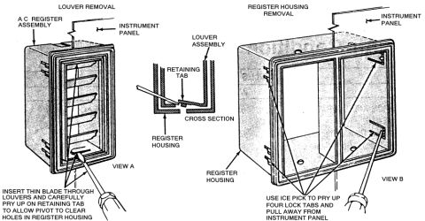




Exploded parts illustration of Bronco integral A/C ducts, vents and control components with Ford part numbers.
Part of 1978-1979 Ford Bronco Exploded Parts Diagrams
This is page 35 from Ford's illustration section 195.1 of the 1973/79 Ford Cars parts catalog, dated November 1984 (marked 'NEW ISSUE'). It is an exploded parts diagram titled 'AIR CONDITIONER CONTROLS and RELATED PARTS, 1978/ Bronco -- Integral A/C.' The illustration (Ford drawing P-12935) shows the dash-mounted air conditioning and heater duct/control components for the 1978-and-later Ford Bronco with factory integral (in-dash) air conditioning. Callouts identify Ford basic part group numbers for the plenum/duct assemblies (18490, 18471, 198680), flexible duct hoses and outlets, register/louver assemblies (19893), duct outlets (19926), the control assembly and related hardware (19A884, 18A367, 9A050, 19C925, 18502, 18541, 18546, 13466, 19B888, 18319, 19B86, 19C827, 19A885), wiring (14401), and a fastener (55923-S, U-361-D). Footnotes indicate which parts are serviced only in, or also serviced in, assembly group 19980 (the A/C control assembly group). A reader can use this diagram to identify part group numbers and the physical arrangement of the A/C/heater ducts, registers, vacuum lines, cables, and control head for a 1978/79 Bronco with integral air conditioning.
Is this accurate? Sign in to help verify it.
Frequently asked questions
- What vehicle does this A/C controls parts diagram cover?
- It is labeled 'AIR CONDITIONER CONTROLS and RELATED PARTS, 1978/ Bronco -- Integral A/C,' from the 1973/79 Ford Cars illustration catalog, Section 195.1, page 35.
- What is the part group number for the A/C registers/louvers shown?
- The register/louver assemblies are called out as part group 19893, and the duct outlets are 19926.
- Which parts are serviced only in assembly group 19980?
- Parts marked with a solid square (■), such as 18502, 18A367, 9A050, 19C925, 18541, 13466, 18546, and 19B888, are serviced only in assy-group 19980; parts marked with the smaller square are also serviced in assy-group 19980.
- What is the Ford illustration number for this diagram?
- The drawing is identified as P-12935, from Illustration Section 195.1 of the 1973/79 Ford Cars catalog, dated November 1984.
- What part number is shown for the fastener at the top of the diagram?
- 55923-S (U-361-D), attaching near the 18490 duct assembly.






No comments yet.