Ford Bronco Transfer Case & Shift Linkage Exploded Diagram - Torque Specs
Reference · 1978-1979 BroncoAll 79 exploded parts diagrams
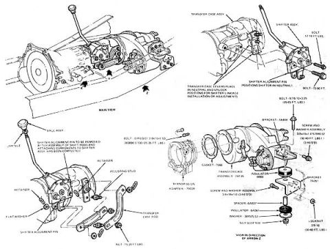
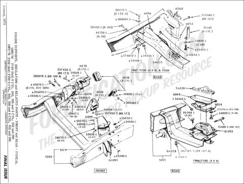
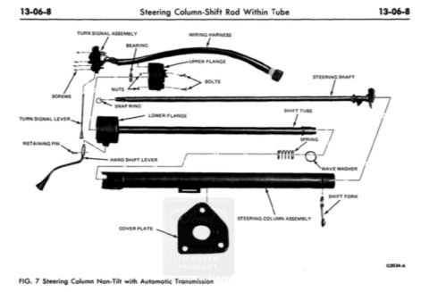



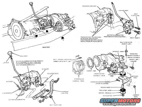
Exploded parts diagram of a transfer case and shifter linkage assembly with part numbers and torque values.
Part of 1978-1979 Ford Bronco Exploded Parts Diagrams
This scanned page is an exploded parts and installation diagram covering a Ford transfer case assembly and its shift linkage. It contains four illustrations: a main view showing the transmission/transfer case installed in the vehicle, a detail of the shifter assembly mounting to the transfer case, an exploded view of the shifter/shift rod linkage components, and an exploded view of the transfer case, adapter, gasket, and mounting bracket hardware (viewed in the direction of arrow Z). Callouts identify the transfer case assembly (7A195), gasket (7086), transmission adapter (7A039), brackets (7A444, 7A091), insulators (6068, 6A061), spacer (6A027), washer (384505-S2), and fasteners with torque specifications: shifter bolts 12-16 ft-lbs, a 70-90 ft-lb bolt, 3/8-16x1.50 bolts (5 required, 383890-S100) at 25-35 ft-lbs, a 9/16-12 bolt at 55-65 ft-lbs, 3/8-16x1.0 screw-and-washer assemblies (57646-S2, 3 required) at 25-40 ft-lbs, a linkage nut at 15-20 ft-lbs, and a 3/8-16 locknut at 30-40 ft-lbs. Notes explain that a shifter alignment pin positions the shifter in neutral and must be removed after the shift rods are attached, and that the transfer case lever is placed in the neutral/unlock positions for linkage installation or adjustment.
Is this accurate? Sign in to help verify it.
Frequently asked questions
- What is the torque spec for the transfer case shifter assembly bolts?
- The shifter assembly bolts are torqued to 12-16 ft. lbs., and another bolt shown is torqued to 70-90 ft.
- How many bolts hold the transmission adapter/transfer case joint and what is their torque?
- Five 3/8-16x1.50 bolts (part 383890-S100) are required, torqued to 25-35 ft. lbs.
- What is the purpose of the shifter alignment pin?
- The shifter alignment pin positions the shifter in neutral. It is to be removed after assembly of the shift rods and attaching components to the shifter assembly has been completed.
- How should the transfer case lever be positioned when installing or adjusting the shift linkage?
- The transfer case lever is placed in the neutral and unlock positions for shifter linkage installation or adjustments.
- What part numbers are shown for the transfer case and related components?
- Transfer case assembly 7A195, gasket 7086, transmission adapter 7A039, brackets 7A444 and 7A091, insulators 6068 and 6A061, spacer 6A027, and washer 384505-S2.






No comments yet.