Home/
Registry/
Ford/
Bronco/
1992-1996/
1995 Ford Bronco/
Photo
supermotors.net/registry/media/419403
Right vs Wrong Lifting Technique Diagram - Ford Bronco Service Illustration

Reference · 1992-1996 BroncoAll 143 service procedures


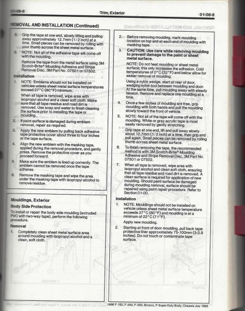








Instructional Figure 1 RIGHT and Figure 2 WRONG diagram showing correct versus incorrect prying technique.
Part of 1992-1996 Ford Bronco Service Procedures
This document is a simple two-panel instructional illustration comparing a correct and an incorrect technique. Figure 1, captioned "RIGHT," depicts a component (appearing to be a battery or similar part) being lifted or held with a two-point carrier/clamp tool, with two upward arrows showing balanced, even lifting force applied on both sides. Figure 2, captioned "WRONG," shows the same component being lifted or pried from only one side, with a single large upward arrow and an angled arrow indicating a prying or tipping action against the hold-down hardware. The only text visible in the scan consists of the labels "FIGURE 1," "FIGURE 2," "RIGHT," and "WRONG." There are no part numbers, torque values, model years, or written instructions. The image was uploaded to a 1995 Ford Bronco gallery alongside a companion scan titled "5-point mounting.gif," suggesting it is one page of a mounting or removal procedure, likely illustrating proper handling technique (even, straight lifting versus one-sided prying). A reader learns visually that the correct method uses balanced two-point lifting while the incorrect method involves single-sided prying or angled force.
Is this accurate? Sign in to help verify it.
Frequently asked questions
- What does Figure 1 in this diagram show?
- Figure 1 is labeled "RIGHT" and shows the component being lifted with a two-point clamp/carrier, with upward arrows on both sides indicating a straight, balanced lift.
- What does Figure 2 in this diagram show?
- Figure 2 is labeled "WRONG" and shows the component being lifted or pried from one side only, with a single large upward arrow and an angled arrow indicating incorrect one-sided force.
- Does this document contain any part numbers, torque specs, or written instructions?
- No. The only text visible is "FIGURE 1," "FIGURE 2," "RIGHT," and "WRONG." All other information is conveyed through the illustrations.
- What is the correct technique according to this illustration?
- According to the "RIGHT" panel, the correct technique is to lift straight up evenly from both sides using a two-point grip, rather than prying from one side as shown in the "WRONG" panel.






No comments yet.