Home/
Registry/
Suzuki/
Samurai/
1986-1995/
“Little Blue”/
Photo
supermotors.net/registry/media/420683
Suzuki Clearance & Side Marker Light Wiring Diagram - 15A Fuse 13 Circuit
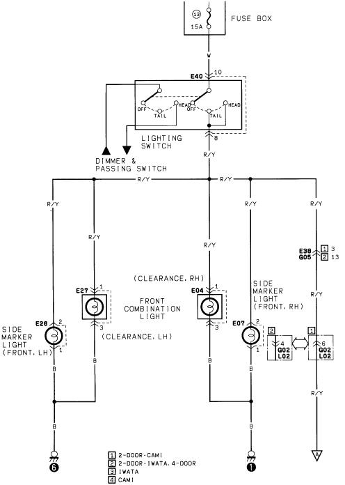
Wiring diagram of the front lighting circuit showing the lighting switch, front combination lights and side marker lights with R/Y wires.
This is a scanned wiring diagram for the clearance (parking) lamps and front side marker lights circuit. Power originates at fuse position 13 (15A) in the fuse box, feeding through a White (W) wire to pin 10 of connector E40 at the lighting switch, which has OFF, TAIL, and HEAD positions and ties into the dimmer & passing switch. From switch pin 8, a Red/Yellow (R/Y) wire distributes power to four lamp branches: the left front combination light clearance bulb (connector E27, clearance LH), the right front combination light clearance bulb (connector E04, clearance RH), the front left side marker light (connector E26), and the front right side marker light (connector E07). All lamps ground through Black (B) wires to chassis ground points 6 and 1. Intermediate connectors E38/G05 (pins 3 and 13) and G02/L02 (pins 4 and 6) are shown on the right-hand branch. A legend keys variant applicability: [1] 2-door CAMI-built, [2] 2-door IWATA-built and 4-door, [3] IWATA, [4] CAMI. A reader can learn the fuse rating, wire colors, connector identifiers/pins, and grounding for the clearance and side marker lamp circuit.
Is this accurate? Sign in to help verify it.
Frequently asked questions
- What fuse powers the clearance and side marker lights in this diagram?
- Fuse position 13 in the fuse box, rated 15A, feeds the circuit via a White (W) wire to the lighting switch.
- What wire color feeds the clearance and side marker lamps?
- A Red/Yellow (R/Y) wire from pin 8 of the lighting switch supplies all four lamps; each lamp grounds through a Black (B) wire.
- Which connectors are used for the front side marker lights?
- E26 for the front left side marker light and E07 for the front right side marker light, each using pins 1 and 2.
- Which connectors serve the front clearance lamps?
- E27 for the left clearance bulb and E04 for the right clearance bulb, both part of the front combination lights, using pins 1 and 3.
- What do the numbered legend symbols mean?
- [1] = 2-door CAMI, [2] = 2-door IWATA and 4-door, [3] = IWATA, [4] = CAMI, indicating which build variant each connector option applies to.
Comments
More from this build














No comments yet.