Home/
Registry/
Ford/
Taurus/
1996-1999/
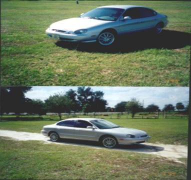
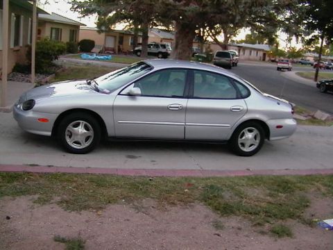
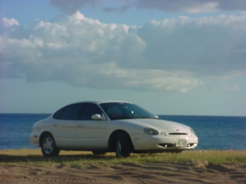
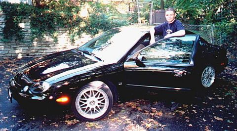
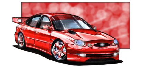
1997 Ford Taurus/
Photo
supermotors.net/registry/media/512327
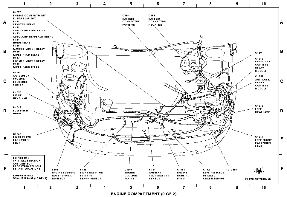
1997 Ford Taurus/Sable Engine Compartment Electrical Component Locations (2 of 2)
Reference · 1996-1999 TaurusAll 33 wiring diagrams
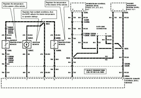
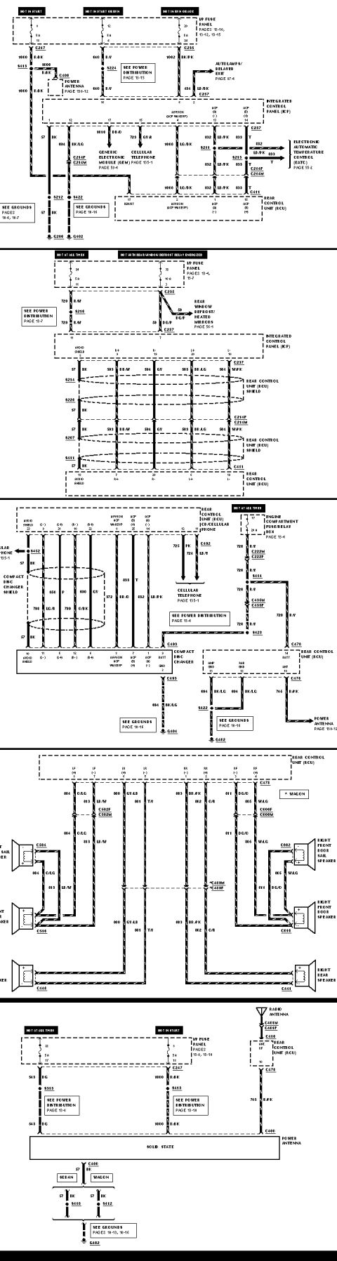
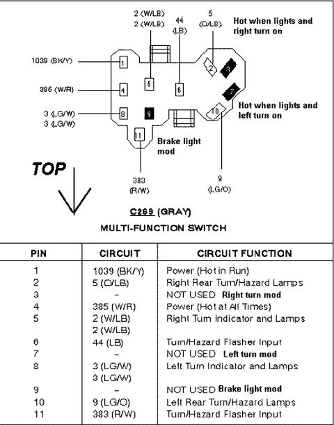

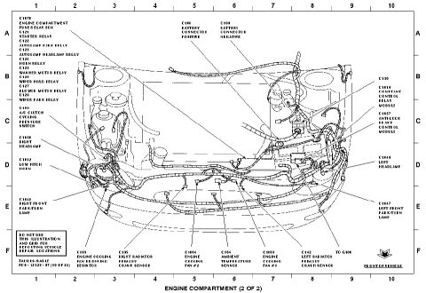
Engine compartment wiring harness connector-location diagram identifying relays, modules and connectors on a numbered grid.
Part of 1996-1999 Ford Taurus Wiring Diagrams
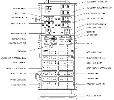
This is page 10 of 24 from the Ford Taurus/Sable electrical component location manual (document code FCS-12123-97), showing 'Engine Compartment (2 of 2)'. It is an overhead line-art illustration of the front of the vehicle with a lettered/numbered locator grid (columns 1-10, rows A-F). Callout lines identify the physical locations of electrical connectors and components in the engine compartment, including the C1070 engine compartment fuse/relay box and its relays (C121 starter relay, C122 autolamp park relay, C123 autolamp headlamp relay, C124 horn relay, C125 washer motor relay, C126 wiper hi/lo relay, C127 blower motor relay, C128 wiper park relay), battery connectors (C108 positive, C109 negative), the C160 A/C clutch cycling pressure switch, headlamps (C1050 right, C1049 left), park/turn lamps (C1048 right, C1047 left), C1012 low pitch horn, C1019 constant control relay module, C1057 anti-lock brake control module, cooling fans (C1063 fan #1, C1064 fan #2) and their C193 dropping resistor, C164 ambient temperature sensor, radiator primary crash sensors (C195 right, C142 left), ground G100, and connector C130. A boxed note warns not to use the illustration/grid for reporting vehicle repair locations.
Is this accurate? Sign in to help verify it.
Frequently asked questions
- Where is the anti-lock brake control module connector on a 1997 Taurus/Sable?
- The C1057 anti-lock brake control module is shown on the left side of the engine compartment (right side of the diagram), near grid area C8-D8.
- Which relays are located in the engine compartment fuse/relay box (C1070)?
- The diagram lists C121 starter relay, C122 autolamp park relay, C123 autolamp headlamp relay, C124 horn relay, C125 washer motor relay, C126 wiper hi/lo relay, C127 blower motor relay, and C128 wiper park relay.
- What are the connector numbers for the engine cooling fans?
- C1063 is engine cooling fan #1 and C1064 is engine cooling fan #2; C193 is the engine cooling fan dropping resistor.
- Where are the battery connectors identified?
- C108 is the battery connector positive and C109 is the battery connector negative, both shown at the top center of the engine compartment illustration.
- What are the crash sensor connector IDs?
- C195 is the right radiator primary crash sensor and C142 is the left radiator primary crash sensor.
No comments yet.