Home/
Registry/
Ford/
Taurus/
1996-1999/
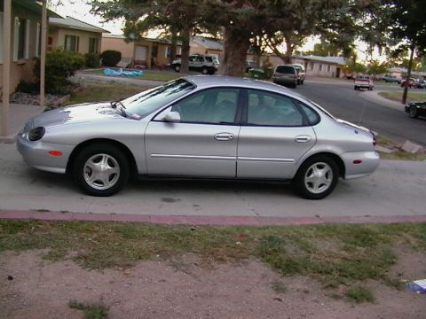
1997 Ford Taurus/
Photo
supermotors.net/registry/media/262747
1997 Ford Taurus ABS Wiring Diagram - Anti-Lock Brake Module, Sensors & Fuses

Electrical wiring diagram spanning several panels showing relays, motor windings and integrated control modules with circuit references.
This document is a Ford anti-lock brake system (ABS) wiring diagram, uploaded for a 1997 Ford Taurus. It shows the complete ABS circuit in three sections. The top and bottom sections depict the power supply from the Engine Compartment Fuse/Relay Box (fuse 13, ABS Module 40 A on circuit 532 O/Y, and fuse 18, ABS Module 30 A on circuit 533 T/R) feeding through connector C1057 into the Anti-Lock Brake Control Module, which internally contains the Solenoid Control Valves Relay, Pump Motor Relay, eight inlet/outlet solenoid valves (left front, right front, left rear, right rear), and solid-state circuitry, with the hydraulic pump motor grounded at G100. The middle section shows the data link network (70 LB/W circuit) connecting the Remote Anti-Theft Personality (RAP) Module, Air Bag Diagnostic Monitor, Generic Electronic Module (GEM), and Data Link Connector to module pin 23, plus all four wheel speed (brake) sensors with their wire circuits and connectors: left front (521 T/O, 522 T/BK, C1001F/M), left rear (518 LG/R, 519 LG/BK, C308F/M), right rear (523 R/K, 524 PK/BK, C310F/M), and right front (516 V/BK, 514 V/R, C1000F/M). A footnote indicates early production 3.0L 4V or 3.4L SHO applicability for certain connectors.
Is this accurate? Sign in to help verify it.
Frequently asked questions
- What fuses power the ABS module on this diagram?
- Two hot-at-all-times fuses in the Engine Compartment Fuse/Relay Box: fuse 13, labeled ABS MODULE 40 A (circuit 532 O/Y), and fuse 18, labeled ABS MODULE 30 A (circuit 533 T/R), both feeding through connector C1057.
- What are the wheel speed sensor wire colors and connectors?
- Left front: 521 T/O and 522 T/BK via C1001F/C1001M; left rear: 518 LG/R and 519 LG/BK via C308F/C308M; right rear: 523 R/K and 524 PK/BK via C222M/C222F and C310F/C310M; right front: 516 V/BK and 514 V/R via C1000F/C1000M.
- What components are inside the Anti-Lock Brake Control Module?
- The module contains the solenoid control valves relay, pump motor relay, inlet and outlet solenoid valves for left front, right front, left rear, and right rear wheels, and solid-state circuitry; the hydraulic pump motor connects to it and grounds at G100.
- How do the wheel speed sensors work per this diagram?
- Variable reluctance sensors and toothed speed indicator rings determine wheel speed. As ring teeth pass the sensor, a pulsing voltage signal is generated and sent to the Anti-Lock Brake Module; the pulses are directly proportional to wheel speed and also assist the PCM in determining shift schedules and EPC pressure.
- What other modules share the ABS data link circuit?
- The 70 LB/W data circuit connects the Remote Anti-Theft Personality (RAP) Module (pin 3, C253), Air Bag Diagnostic Monitor (pin 12, C277), Generic Electronic Module (GEM) (pin 10, C230), and the Data Link Connector (pin 7, C229) to pin 23 of the Anti-Lock Brake Control Module.
Comments
More from this build




No comments yet.