1979 Ford Bronco Wiring Diagram - Gauges, Heater/AC & Blower Circuits (Haynes)
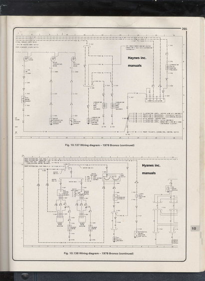
Scanned Haynes manual page showing two 1979 Ford Bronco wiring diagrams with circuit lines and component callouts.
This is page 265 of a Haynes repair manual containing two continuation pages of the factory-style wiring diagram for the 1979 Ford Bronco (Fig. 10.137 and Fig. 10.138). The upper diagram (Fig. 10.137) covers the instrument gauges and emission-related circuits: fuel gauge and sender, water temperature gauge and indicator sender, oil pressure gauge and sender, carburetor float bowl vent solenoids, carburetor throttle emission control solenoid, carburetor valve control solenoid, and throttle actuator, along with splice S-805 feeding illumination lamps, seat belt buckle switch/warning buzzer, washer pump, and the power tailgate window regulator control switch. The lower diagram (Fig. 10.138) covers the heater and air conditioning system: A/C mode switch (with seven switch positions listed), A/C control switch, heater blower switch, blower motor resistors, blower motors, A/C evaporator thermostat, A/C clutch solenoid, plus the 4-wheel-drive indicator lamp, differential lockout indicator lamp switch, and part of the AM radio receiver/speaker circuit. Wire circuit numbers and colors are given throughout (e.g., 16 R-GR, 640 R-Y, 932 BL, 57 BK, 137 Y-BK, 268 R-BK, 270 BK-Y), along with connector identifiers (C-208 through C-616), splices (S-603, S-701, S-805), and grounds (G-601, G-701, G-704, G-705). Power sources include fuse panel positions F-3 and F-12.
Is this accurate? Sign in to help verify it.
Frequently asked questions
- What circuits are shown in Fig. 10.137 for the 1979 Bronco?
- Fig. 10.137 shows the fuel gauge and sender, water temperature gauge and indicator sender, oil pressure gauge and sender, carburetor float bowl vent solenoids, carburetor throttle emission control solenoid, carburetor valve control solenoid, and throttle actuator, plus splice S-805 which feeds illumination lamps, the seat belt buckle switch and warning buzzer, the washer pump, and the power tailgate window regulator control switch.
- What are the A/C mode switch positions on the 1979 Bronco?
- Per the diagram: 1. OFF, 2. VENT, 3. A/C, 4. HI-LO, 5. HEAT, 6. HEAT-DEFROST, 7. DEFROST.
- Which fuse panel positions power the heater/A/C circuits shown?
- The diagram shows power distribution from fuse panel positions F-12 (circuit 137 Y-BK) and F-3 (circuit 181 O), plus connector C-503 (297 BK-GR) and C-408 for the carb emission control solenoid (932 BL).
- What wire color and circuit number feeds the 4-wheel drive indicator lamp?
- Circuit 297 BK-GR feeds through connector C-416 to the 4-wheel drive indicator lamp, then circuit 210 BL runs through C-417 and C-418 to the differential lockout indicator lamp switch.
- What are the heater blower switch positions?
- The heater blower switch (and A/C blower control switch) positions are 1. OFF, 2. LOW, 3. MED, 4. HI, with blower speeds via blower motor resistors on circuits 268 R-BK, 269 BL-R, and 270 BK-Y.
Comments
More from this build






No comments yet.