Technical diagram of front wheel alignment showing caster, cambe…
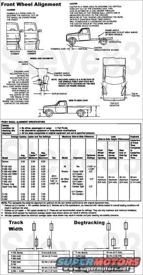
Front Wheel Alignment
IF THE IMAGE IS TOO SMALL, click it.
Wheel alignment measurements describe the angular orientation of the wheel/tire assembly and the steering axis. Caster, camber and toe are the three major, measurable, alignment parameters that most affect tire wear and directional stability. A description of these and other alignment-related parameters follow. It is important to note that the values of these change when a vehicle is loaded (ride height / lean) and driven. Therefore, the specifications shown in this section reflect the static measurement of alignment required so that the vehicle will have an alignment when driven that is most favorable for tire wear and directional stability. .
.  .
. 
Ride Height
The ride height setting of the Twin-I-Beam & Twin-Traction-Beam suspension is critical before any other measurements are taken because it affects caster, camber, toe, included angle, driveline angles, and frame wear. Vehicle Lean is equally critical since it affects the camber split, toe change while driving, and frame wear. Ride height may have been altered or a lean caused by spring aging, suspension/frame damage, suspension modification, overloading, anti-sway bar system damage, or installed accessories. .
.  .
.  .
.  .
.  .
. 
Toe
Toe is intended to change slightly with ride height to provide optimum handling and tire life within the vehicle load range limits. It tends to change toward toe-out as the ride height is lowered. If toe is within specification for the vehicle condition described in the specifications charts, there should be no need to readjust toe setting with varying loads. However, if aftermarket equipment that significantly affects the ride height (i.e., snowplow, second unit bodies, tool boxes) is added, the toe may need to be adjusted. Toe should be maintained at the specified setting with the vehicle in the loaded condition that it experiences for more than 50 percent of its use.
Dogtracking
All F-150-250-350 (4x2) (4x4), Bronco and E-150-250-350 vehicles with single rear wheels (SRW) have, by design, a front track that is wider than the rear track. Front track is the distance between the two front tires, and likewise for the rear. When a vehicle with these track differences is driven on a crowned road, the front may tend to ride higher up the crown than the rear, making these vehicles appear to dogtrack. Dog-tracking may also be a result of frame or rear suspension damage. .
. 
Front End General Inspection
CAUTION: Do not attempt to adjust front wheel alignment without first making a preliminary inspection of the front end parts, and correcting where necessary.
Prior to inspection, fill all fluids to specification. Make sure spare tire or wheel, and related equipment are properly stored. Remove any excessive accumulation of mud, dirt or road deposits from the chassis and underbody. Retain all normal loads in the vehicle. Inflate all tires to the pressure specified on the Safety Compliance Certification Label (usually located on the inside driver's door pillar). Check all tires, making sure they are the same size, ply rating, and load range across each axle.
NOTE: Codes identifying the front and rear spring options and springs are printed on the Safety Standard Certification Label. Springs should be replaced in pairs if one is found to be damaged or worn. If a spring should require replacement because it is damaged, worn or due to a leaning conditioning, it should be replaced only with the same part as specified on the label. In rare instances, the spring codes will not reflect the springs as installed due to a DSO option or assembly plant substitution. If a DSO option number is shown on the certification label, the District Office can establish whether springs are affected. If the factory-installed springs do not agree with the code printed on the Safety Standard Certification Label (right and left spring part number should match), replace the damaged or worn spring with a new spring of the same part number as the damaged or worn spring. It will not be necessary to replace the matching, non-worn or undamaged spring.
1. Inflate all tires to the specified pressure (cold). Check all tires. They should be the same size, ply rating and load range across each axle.
2. Check for excessive wheel bearing end play. Adjust and/or replace the wheel bearings as described in the appropriate section.
3. Check for worn or damaged spindle ball joints. Replace the ball joints when necessary as described in the appropriate section.
4. Check for bent steering linkage or excessively worn joints.
5. Check the steering gear mounting bolts and tighten to the specified torque.
6. Inspect the radius arm to be sure it is not bent or damaged. Inspect the bushings at the radius arm-to-frame attachment for wear and looseness. Repair or replace parts as required.
7. Check other suspension components for damage.
8. Check for aftermarket changes to steering, suspension, wheel and tire components (i.e., competition, heavy duty, etc.). Specifications in this manual do not apply to vehicles with these changes.
See also: .
.  .
. 
Is this accurate? Sign in to help verify it.
Comments
More from this build


No comments yet.