Home/
Registry/
Ford/
Taurus/
1996-1999/
1997 Ford Taurus/
Photo
supermotors.net/registry/media/583907
1997 Ford Taurus Cooling Fan Wiring Diagram - CCRM, EDF/HEDF Relays & PCM

Reference · 1996-1999 TaurusAll 33 wiring diagrams
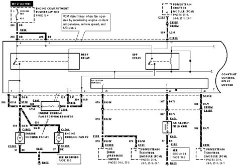
Wiring diagram showing engine cooling fan circuits, HEDF and EDF relays, A/C clutch field coil and color-coded wires.
Part of 1996-1999 Ford Taurus Wiring Diagrams
This is a factory-style wiring diagram page showing the engine cooling fan and A/C clutch control circuit for a Ford vehicle (uploaded as a 1997 Taurus document). Power comes from a 40 A COOLING FAN fuse in the engine compartment fuse/relay box (page 13-6), hot at all times, feeding circuit 226 DB through splice S132 into the Constant Control Relay Module (CCRM), which contains the HEDF relay, EDF relay, and A/C clutch control. A callout explains that the PCM determines when the fan operates by monitoring engine coolant temperature, vehicle speed, and A/C status; the PCM commands the module via circuit 639 LG/P (C1013, C131, C130F/C130M). Outputs include 536 GY/R and 538 GY/R (through the engine cooling fan dropping resistor at C193) to Engine Cooling Fan #1 (C1063) and Fan #2 (C1064), grounded via 57 BK at S145 to G105 (grounds page 10-5); 879 DG/W to the A/C high pressure switch (C1069, pages 54-2, 55-2) and PCM pin 40; 347 BK/V to the A/C clutch field coil (C161) grounded at S108/G103 (grounds page 10-3); and 331 PK/V back to PCM pin 69. Circuit numbers, wire colors, splices, and connector IDs are all labeled.
Is this accurate? Sign in to help verify it.
Frequently asked questions
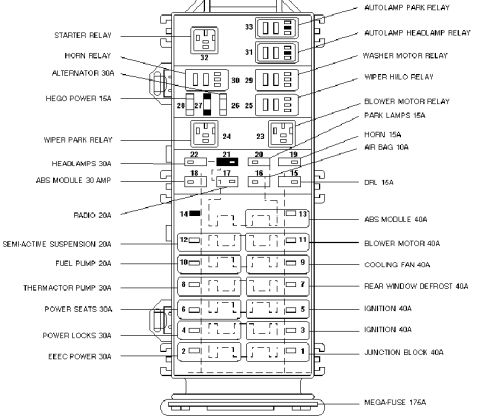
- What fuse powers the cooling fan circuit in this diagram?
- A 40 A COOLING FAN fuse in the engine compartment fuse/relay box (page 13-6), which is hot at all times, feeding circuit 226 DB.
- What controls when the cooling fans operate?
- The Powertrain Control Module (PCM) determines when the fan operates by monitoring engine coolant temperature, vehicle speed, and A/C status. It signals the Constant Control Relay Module via circuit 639 LG/P.
- What relays are inside the Constant Control Relay Module?
- The CCRM contains the HEDF relay, the EDF relay, and the A/C clutch control.
- What wire colors feed the engine cooling fans?
- Circuit 536 GY/R feeds the fans directly, and 538 GY/R feeds through the engine cooling fan dropping resistor (connector C193). Fan #1 uses connector C1063 and Fan #2 uses C1064; both ground through 57 BK at splice S145 to ground G105.
- How is the A/C clutch wired in this circuit?
- Circuit 347 BK/V runs through connector C161 to the A/C clutch field coil, which grounds via 57 BK through splice S108 to ground G103. Circuit 879 DG/W connects the A/C high pressure switch (C1069) and PCM pin 40, and 331 PK/V returns to PCM pin 69.

No comments yet.