Home/
Registry/
Ford/
Taurus/
1996-1999/
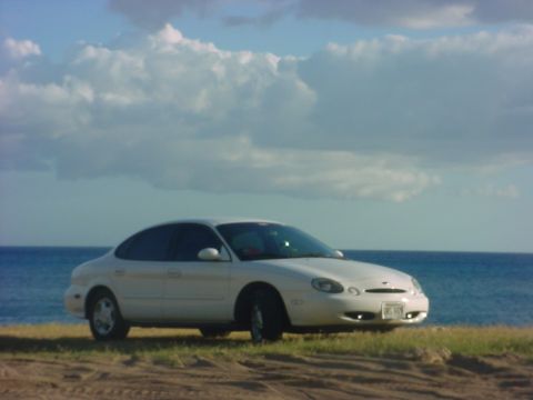
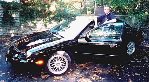
1997 Ford Taurus/
Photo
supermotors.net/registry/media/570641
Ford Taurus SARC Module Connector C450 Pinout - Wire Colors & Circuits
Reference · 1996-1999 TaurusAll 33 wiring diagrams
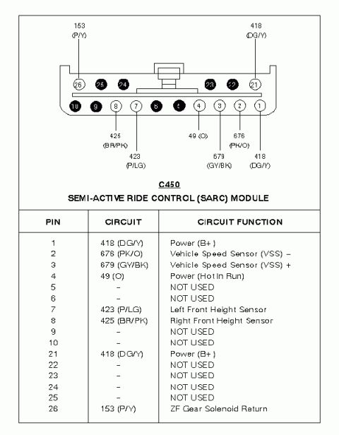
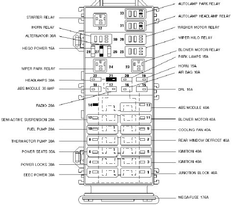

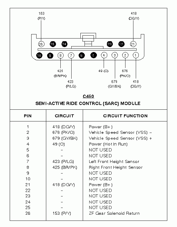
Wiring diagram of the Semi-Active Ride Control (SARC) module C450 connector showing pin numbers, color-coded circuits and functions.
Part of 1996-1999 Ford Taurus Wiring Diagrams
This document is a connector pinout reference for connector C450, the Semi-Active Ride Control (SARC) Module. It shows a face-view drawing of the multi-pin connector with two rows of cavities (pins 1-10 on the bottom row and pins 21-26 on the top row) and wire callouts identifying circuit numbers and wire colors for the populated cavities. Below the drawing, a table lists each pin with its circuit number, wire color code, and circuit function. Populated circuits include: pin 1 and pin 21, circuit 418 (Dark Green/Yellow), Power (B+); pin 2, circuit 676 (Pink/Orange), Vehicle Speed Sensor (VSS) negative; pin 3, circuit 679 (Gray/Black), VSS positive; pin 4, circuit 49 (Orange), Power (Hot In Run); pin 7, circuit 423 (Purple/Light Green), Left Front Height Sensor; pin 8, circuit 425 (Brown/Pink), Right Front Height Sensor; and pin 26, circuit 153 (Purple/Yellow), ZF Gear Solenoid Return. Pins 5, 6, 9, 10, and 22-25 are marked NOT USED. A reader can use this to identify wires at the SARC module connector for diagnosis or repair of the semi-active suspension system.
Is this accurate? Sign in to help verify it.
Frequently asked questions
- What connector is shown in this diagram?
- Connector C450, which connects to the Semi-Active Ride Control (SARC) Module.
- Which pins on C450 provide power to the SARC module?
- Pin 1 and pin 21 are Power (B+) on circuit 418 (DG/Y wire), and pin 4 is Power (Hot In Run) on circuit 49 (O wire).
- Which pins carry the Vehicle Speed Sensor signals?
- Pin 2 is VSS negative on circuit 676 (PK/O) and pin 3 is VSS positive on circuit 679 (GY/BK).
- Where do the front height sensor circuits connect?
- Pin 7 is the Left Front Height Sensor on circuit 423 (P/LG) and pin 8 is the Right Front Height Sensor on circuit 425 (BR/PK).
- Which pins of connector C450 are not used?
- Pins 5, 6, 9, 10, 22, 23, 24, and 25 are marked NOT USED.
No comments yet.