Home/
Registry/
Ford/
Taurus/
1996-1999/
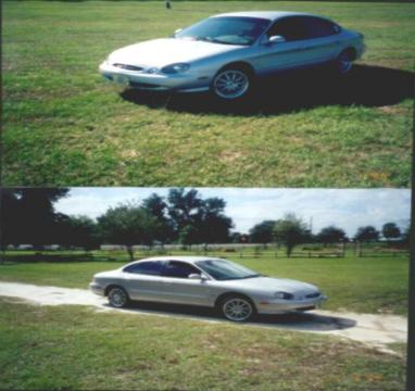
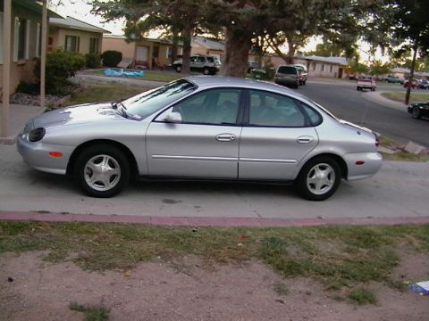
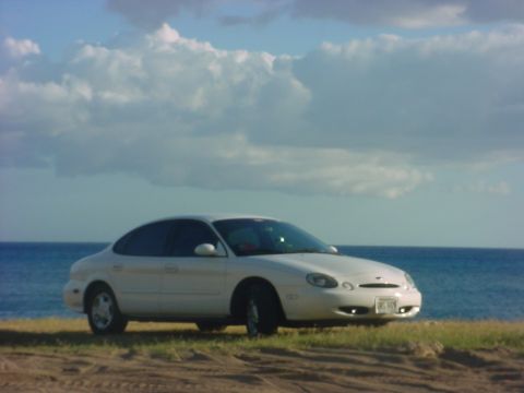
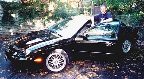
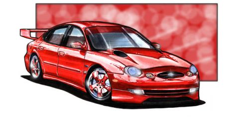
1997 Ford Taurus/
Photo
supermotors.net/registry/media/588337
Ford Taurus DRL Module Connector C186 Pinout - Daytime Running Lamps Wiring

Reference · 1996-1999 TaurusAll 33 wiring diagrams
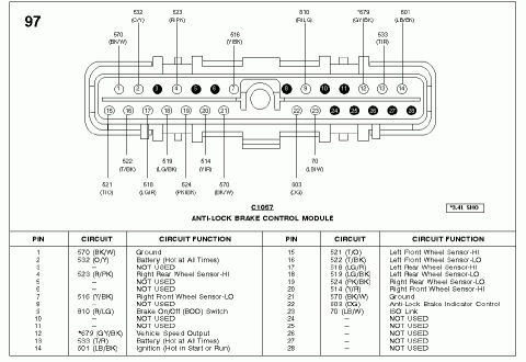
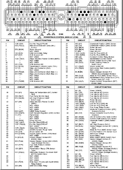
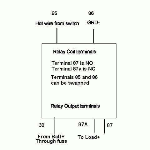
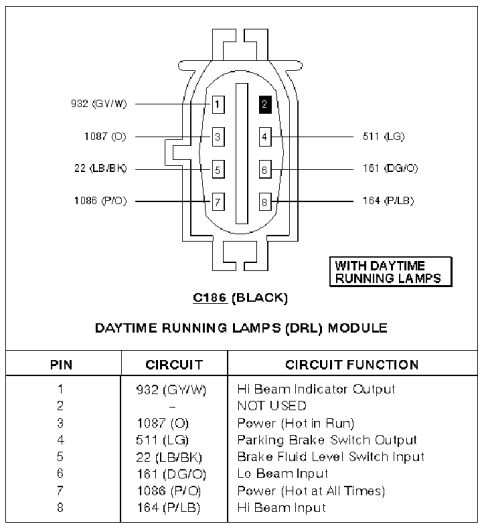
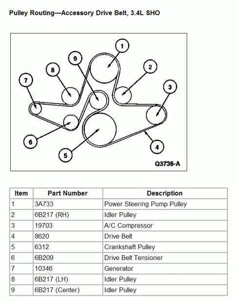
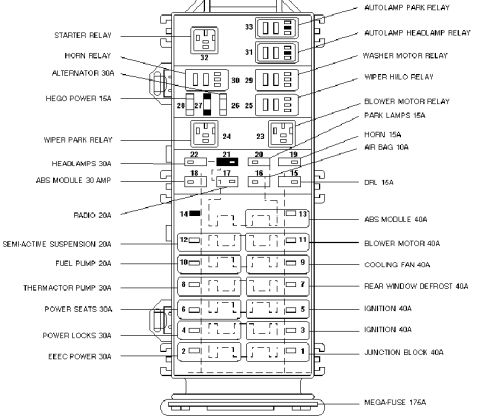
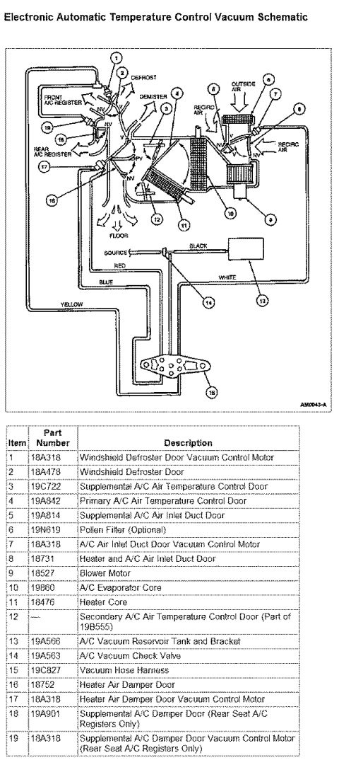

Wiring diagram of the Daytime Running Lamps (DRL) module C186 connector with pin numbers, color-coded circuits and functions.
Part of 1996-1999 Ford Taurus Wiring Diagrams
This document is a connector pinout reference for the Daytime Running Lamps (DRL) module connector C186 (black), applicable to vehicles equipped with daytime running lamps. It includes a face-view illustration of the 8-cavity oval connector showing pin positions, each labeled with its circuit number and wire color code. Below the diagram, a table lists each pin, its circuit number and wire color, and its function: Pin 1 is circuit 932 (gray/white) for the Hi Beam Indicator Output; Pin 2 is not used; Pin 3 is circuit 1087 (orange) providing power hot in run; Pin 4 is circuit 511 (light green) for the Parking Brake Switch Output; Pin 5 is circuit 22 (light blue/black) for the Brake Fluid Level Switch Input; Pin 6 is circuit 161 (dark green/orange) for the Lo Beam Input; Pin 7 is circuit 1086 (pink/orange) providing power hot at all times; and Pin 8 is circuit 164 (pink/light blue) for the Hi Beam Input. A reader can use this to identify wires at the DRL module for testing headlight, parking brake, and brake fluid level circuits, or diagnosing DRL system faults. The document itself shows no year, make, or model, but it was uploaded for a 1997 Ford Taurus.
Is this accurate? Sign in to help verify it.
Frequently asked questions
- What is connector C186 on this diagram?
- C186 is the black 8-pin connector for the Daytime Running Lamps (DRL) Module, used on vehicles equipped with daytime running lamps.
- Which pin on the DRL module provides constant power?
- Pin 7, circuit 1086 (P/O), is Power (Hot at All Times). Pin 3, circuit 1087 (O), is Power (Hot in Run).
- What wire color is the low beam input to the DRL module?
- The Lo Beam Input is on Pin 6, circuit 161, with a dark green/orange (DG/O) wire.
- Which pins relate to the parking brake and brake fluid level?
- Pin 4, circuit 511 (LG), is the Parking Brake Switch Output, and Pin 5, circuit 22 (LB/BK), is the Brake Fluid Level Switch Input.
- Are all 8 pins of the DRL module connector used?
- No. Pin 2 is marked NOT USED; the other seven pins carry circuits.

No comments yet.