Home/
Registry/
Ford/
Taurus/
1996-1999/
1997 Ford Taurus/
Photo
supermotors.net/registry/media/653986
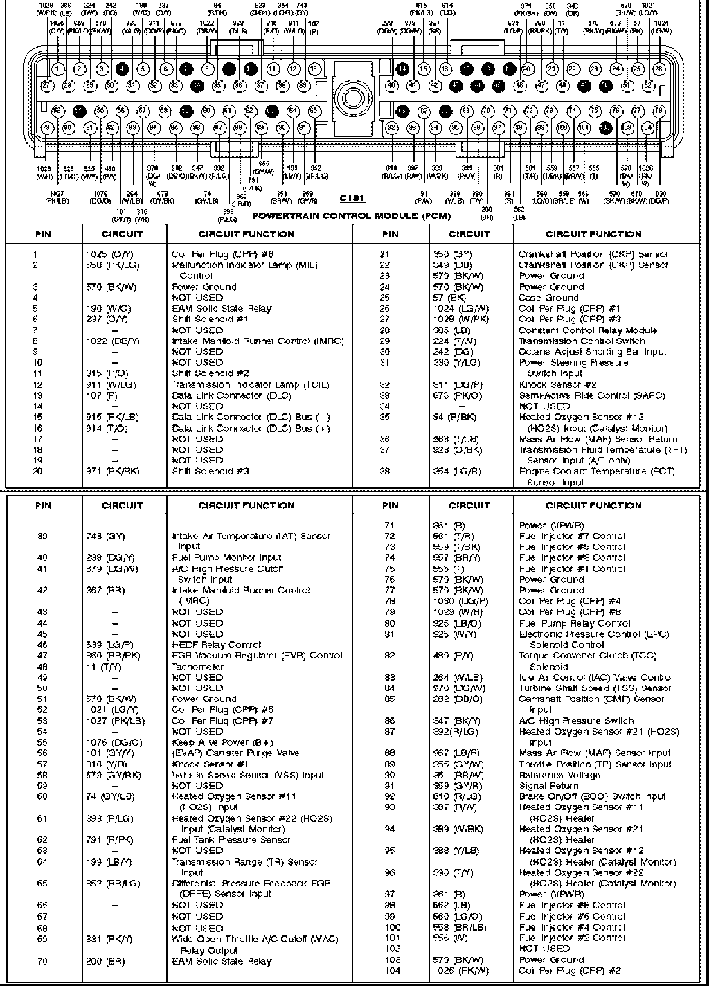
1996 Ford Taurus SHO PCM 104-Pin Connector C191 Complete Pinout Diagram
Reference · 1996-1999 TaurusAll 33 wiring diagrams
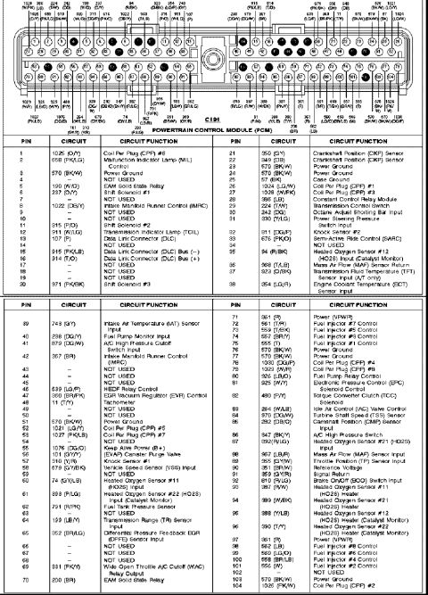
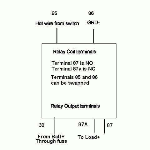
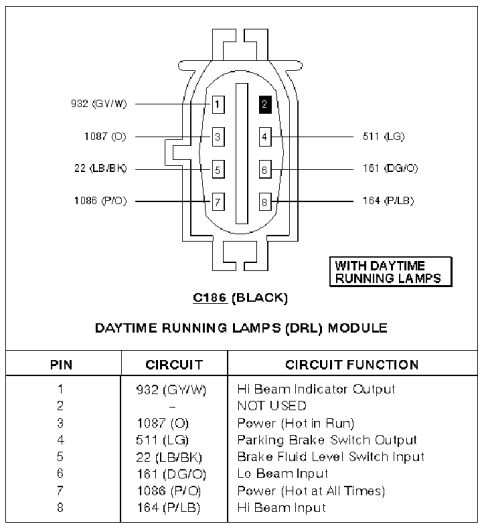
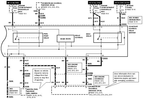
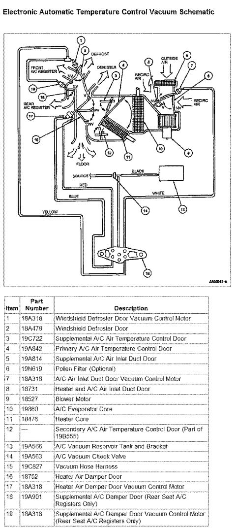

Ford Powertrain Control Module (PCM) connector pinout table listing each pin, circuit number, wire color and function (sensors, solenoids, grounds, MIL, relays).
Part of 1996-1999 Ford Taurus Wiring Diagrams
This document is a complete pinout reference for connector C191, the 104-pin Powertrain Control Module (PCM) connector, on a Ford vehicle (uploaded as a 1996 PCM pinout for a Ford Taurus). A connector-face illustration at the top shows the physical layout of pins 1-104 with circuit numbers and wire color abbreviations called out for each cavity. Two large tables list every pin number, its circuit number and wire color code, and its circuit function. Functions covered include eight Coil Per Plug (CPP) outputs (#1-#8), eight fuel injector control circuits (#1-#8), power grounds, VPWR power feeds, Keep Alive Power (B+), Case Ground, four heated oxygen sensor inputs and four HO2S heater circuits, MAF sensor input/return, TP sensor, IAT, ECT, CMP, CKP, knock sensors #1 and #2, IAC valve control, EGR (EVR and DPFE), EVAP purge, fuel pump relay/monitor, transmission controls (shift solenoids #1-#3, TCC, EPC, TFT, TSS, TR sensor, TCIL), Data Link Connector circuits, A/C high pressure switch and WAC relay, brake on/off switch, power steering pressure switch, Semi-Active Ride Control, tachometer, and numerous 'NOT USED' pins. A reader can identify any PCM pin's circuit number, wire color, and function for diagnosis or wiring repair.
Is this accurate? Sign in to help verify it.
Frequently asked questions
- What connector does this pinout cover?
- It covers C191, the 104-pin Powertrain Control Module (PCM) connector, listing every pin's circuit number, wire color, and function.
- Which PCM pins are power grounds?
- Pins 3, 23, 24, 51, 76, 77, and 103 are Power Ground, all circuit 570 (BK/W). Pin 25 (57, BK) is Case Ground.
- Which pins control the fuel injectors?
- Pin 75 = Injector #1 (555 T), 101 = #2 (556 W), 74 = #3 (557 BR/Y), 100 = #4 (558 BR/LB), 73 = #5 (559 T/BK), 99 = #6 (560 LG/O), 72 = #7 (561 T/R), and 98 = #8 (562 LB).
- Where are the Coil Per Plug (CPP) outputs on the PCM connector?
- CPP #1 = pin 26 (1024 LG/W), #2 = pin 104 (1026 PK/W), #3 = pin 27 (1028 W/PK), #4 = pin 78 (1030 DG/P), #5 = pin 52 (1021 LG/Y), #6 = pin 1 (1025 O/Y), #7 = pin 53 (1027 PK/LB), #8 = pin 79 (1029 W/R).
- Which pin is Keep Alive Power and which pins are VPWR?
- Pin 55 is Keep Alive Power (B+), circuit 1076 (DG/O). Pins 71 and 97 are Power (VPWR), circuit 361 (R).



No comments yet.