Home/
Registry/
Ford/
Taurus/
1996-1999/
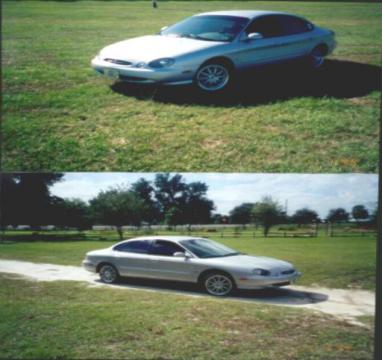
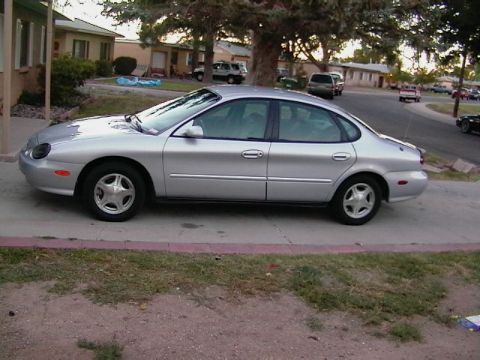
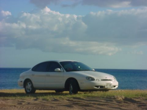
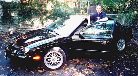
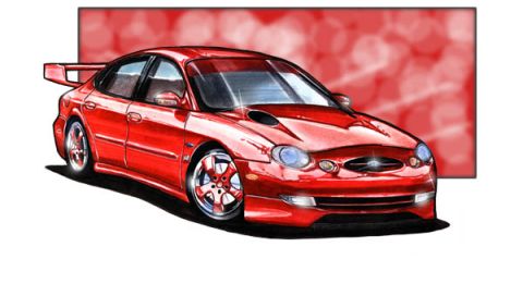
1997 Ford Taurus/
Photo
supermotors.net/registry/media/692376
1997 Ford Taurus ABS Control Module C1057 Connector Pinout & Wire Colors

Reference · 1996-1999 TaurusAll 33 wiring diagrams
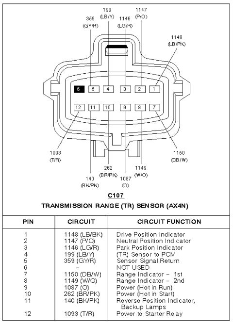
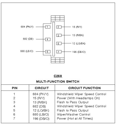
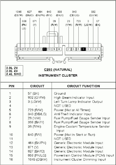
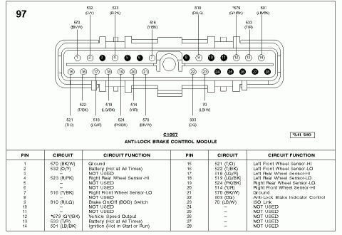
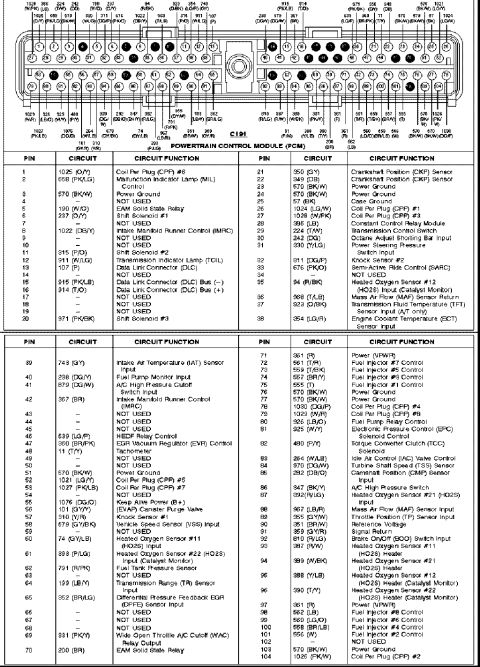
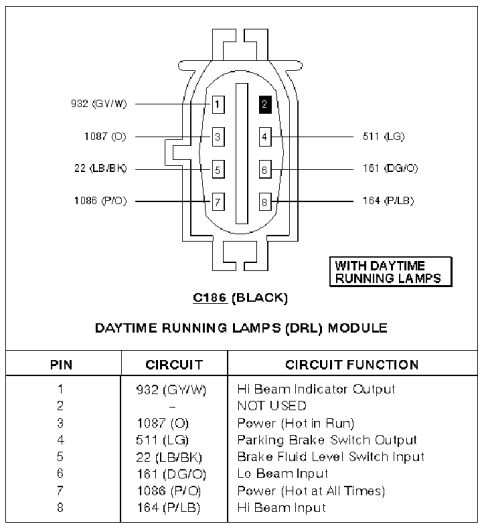
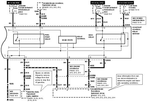

Wiring diagram of the anti-lock brake control module C1057 connector showing pins, color-coded circuits and functions.
Part of 1996-1999 Ford Taurus Wiring Diagrams
This document is a connector pinout diagram and table for connector C1057, the Anti-Lock Brake Control Module, labeled "97" (1997) with a footnote box indicating "*3.4L SHO" applicability for circuit 679. The diagram shows a 28-pin connector: pins 1-14 on the top row and 15-28 on the bottom row, with unused pins shown filled in. Wire circuit numbers and color codes are called out around the connector drawing. The accompanying table lists each pin, its circuit number and wire color, and its function. Key circuits include grounds (570 BK/W, pins 1 and 21), battery feeds hot at all times (532 O/Y pin 2, 533 T/R pin 13), ignition hot in start or run (601 LB/BK pin 14), the Brake On/Off (BOO) switch (810 R/LG pin 9), Vehicle Speed Output (*679 GY/BK pin 12), Anti-Lock Brake Indicator Control (603 DG pin 22), ISO Link (70 LB/W pin 23), and all four wheel speed sensor HI/LO pairs (pins 4, 7, 15-20). Pins 3, 5, 6, 8, 10, 11, and 24-28 are not used. Useful for diagnosing ABS wiring, wheel speed sensor circuits, and module power/ground issues.
Is this accurate? Sign in to help verify it.
Frequently asked questions
- What connector is C1057 on a 1997 Ford Taurus?
- C1057 is the 28-pin connector for the Anti-Lock Brake Control Module, as shown in this pinout diagram labeled '97'.
- Which pins are the ground circuits on the ABS module connector?
- Pins 1 and 21, both circuit 570 with black/white (BK/W) wires, are Ground.
- Where are the wheel speed sensor circuits on connector C1057?
- Pin 4 (523 R/PK) Right Rear-HI, pin 19 (524 PK/BK) Right Rear-LO, pin 20 (514 Y/R) Right Front-HI, pin 7 (516 Y/BK) Right Front-LO, pin 15 (521 T/O) Left Front-HI, pin 16 (522 T/BK) Left Front-LO, pin 17 (518 LG/R) Left Rear-HI, and pin 18 (519 LG/BK) Left Rear-LO.
- Which pin carries the brake pedal (BOO) switch signal?
- Pin 9, circuit 810 with a red/light green (R/LG) wire, is the Brake On/Off (BOO) Switch input.
- Which pins on C1057 are not used?
- Pins 3, 5, 6, 8, 10, 11, 24, 25, 26, 27, and 28 are listed as NOT USED.

No comments yet.