1988 Ford F-150 4.9L EEC-IV Wiring Diagram - ECU Pinout & Sensor Wire Colors
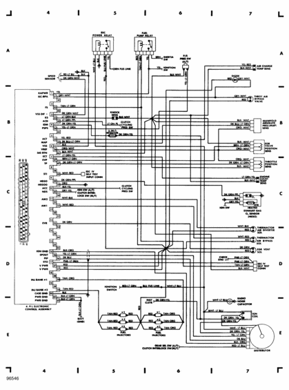
Wiring diagram for the 4.9L EFI EEC control system showing relays, sensors, injectors, and color-coded circuits.
This document is an EEC-IV engine control wiring diagram for the Ford 4.9L inline-six engine, labeled "4.9L ELECTRONIC CONTROL ASSEMBLY." It shows the full 60-pin ECU connector pinout with signal names and wire colors, including power feeds (KAPWR pin 1 YEL, V PWR pins 37/57 RED), grounds (CASE GND pin 20 BLK, PWR GND pins 40/60 BLK-LT GRN), sensor inputs (ACT, MAP, VSS, ECT, EVP, TP, KS knock sensor, HEGO oxygen sensor, PSPS power steering pressure switch), and outputs (ISC-BPA idle speed control, EVR, SPOUT, PIP, injector banks #1 TAN-ORG and #2 TAN-RED). Circuits are traced to the EEC power relay, fuel pump relay, inertia switch, ignition switch, speed sensor, knock sensor with 2.2KΩ resistor, clutch cycling pressure switch, and the EEC-IV self-test connectors (STI and STO with the check engine light). Right-side devices include the air charge temperature sensor, throttle air bypass valve, MAP sensor, EGR valve position sensor, throttle position sensor, engine coolant temperature sensor, heated O2 sensor (HEGO), thermactor air diverter and bypass solenoids, EGR vent solenoid, radio noise capacitor, ignition coil, and distributor. Six fuel injectors (#1-#6) are shown with their wire colors. Diagram number 96546 appears at the bottom left. Useful for tracing EEC-IV circuits and diagnosing sensor/injector wiring on the 4.9L EFI six.
Is this accurate? Sign in to help verify it.
Frequently asked questions
- What are the injector wire colors on the 4.9L EEC-IV system?
- Injector Bank #1 (ECU pin 58) is TAN-ORG serving injectors #1, #3, #5 (RED/TAN-ORG), and Injector Bank #2 (pin 59) is TAN-RED serving injectors #2, #4, #6 (TAN-RED/RED).
- Which ECU pins provide power and ground on the 4.9L electronic control assembly?
- KAPWR is pin 1 (YEL), V PWR is pins 37 and 57 (RED), CASE GND is pin 20 (BLK), PWR GND is pins 40 and 60 (BLK-LT GRN, going to BATT GND), and IGN GND is pin 16 (BLK-ORG).
- What wire colors go to the throttle position sensor (TP)?
- The throttle position sensor uses ORG-WHT (VREF), DK GRN-LT GRN (TP signal, ECU pin 47), and BLK-WHT (signal return).
- How is the fuel pump relay wired in this diagram?
- The fuel pump relay connects with RED, TAN-LT GRN (FS, ECU pin 22) and YEL wires; a BRN wire runs to the inertia switch and a YEL wire to the ignition switch, with BLK-WHT and YEL-LT GRN circuits also shown.
- What wires connect to the distributor?
- The distributor connects via WHT-LT BLU, DK GRN-YEL, YEL-LT GRN (SPOUT), DK BLU (PIP), BLK-ORG, and RED-LT BLU wires.
Comments
More from this build




No comments yet.