Home/
Registry/
Ford/
Mustang/
2005-2014/
“SHELBY GT500”/
Photo
supermotors.net/registry/media/655660
Ford Headlamp Assembly Removal Diagram - Retainer Pins & Connector (GN0906-A)

Reference · 2005-2014 MustangAll 52 service procedures
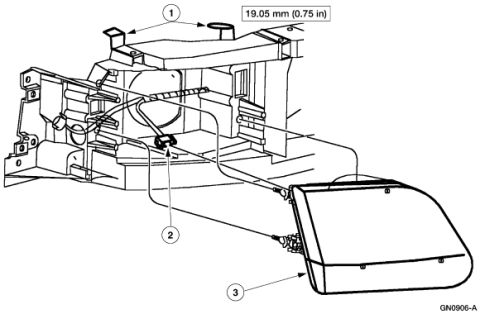
Service illustration of a headlamp assembly and mounting with numbered callouts and a 19.05 mm (0.75 in) gap dimension.
Part of 2005-2014 Ford Mustang Service Procedures
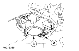
This document is a single exploded-view line illustration showing removal or installation of a headlamp assembly from the front of a vehicle. The drawing depicts the front corner of the vehicle structure (radiator support/front fascia area) with the headlamp assembly pulled outward from its opening. Three numbered callouts identify components: callout 1 points to two retaining pins or rods at the top of the headlamp mounting area, callout 2 points to the bulb electrical connector and wiring behind the lamp opening, and callout 3 identifies the headlamp assembly itself. A dimension note of 19.05 mm (0.75 in) is given, apparently indicating how far a retaining component must be lifted or pulled during the procedure. The illustration carries the Ford graphic reference number GN0906-A in the lower right corner. No text legend, torque specifications, part numbers, or model/year applicability statements appear on the page; the image is purely a pictorial service illustration intended to accompany a written headlamp removal procedure. A reader can learn the general arrangement of the headlamp retainers, connector, and assembly, and the specified pull-up distance for the retainers.
Is this accurate? Sign in to help verify it.
Frequently asked questions
- How far do the headlamp retainer pins need to be pulled up?
- The diagram specifies 19.05 mm (0.75 in), shown with an arrow pointing to the retaining pins at callout 1.
- What components are identified in this headlamp removal diagram?
- Three numbered callouts: 1: the two retaining pins/rods at the top of the headlamp mounting area, 2, the electrical connector/wiring behind the lamp, and 3, the headlamp assembly itself.
- Does the headlamp have an electrical connector that must be disconnected?
- Yes, callout 2 in the illustration points to a wiring connector located behind the headlamp opening.
- What is the reference number of this illustration?
- The illustration is marked GN0906-A in the lower right corner.
No comments yet.