Home/
Registry/
Ford/
Mustang/
2005-2014/
“SHELBY GT500”/
Photo
supermotors.net/registry/media/655661
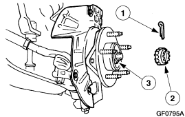
Ford Front Wheel Hub & Knuckle Exploded Diagram - Hub Retainer & Snap Ring
Reference · 2005-2014 MustangAll 52 service procedures
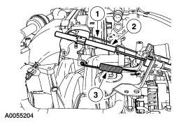
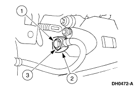
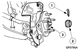
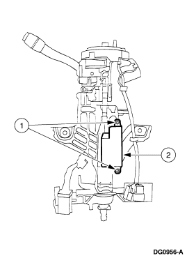









Service illustration of a front wheel hub on the vehicle showing the cotter pin and bearing with numbered callouts.
Part of 2005-2014 Ford Mustang Service Procedures
This document is a single exploded-view service illustration showing a front wheel hub and steering knuckle assembly. The line drawing depicts the knuckle mounted to the suspension, with the hub flange and wheel studs visible (callout 3). Two components are shown removed from the assembly: a small snap ring or retainer clip (callout 1) and a splined nut or hub retainer (callout 2), each indicated with arrows pointing to their installed positions on the hub/axle. The figure carries the Ford illustration reference code GF0795A in the lower right corner. No text legend, torque specifications, part numbers, or written procedure steps appear on this page, so it likely accompanies a multi-page hub or wheel bearing removal/installation procedure whose legend identifies the numbered components. A reader can learn the relative positions and order of the retaining hardware on the hub assembly, and how the clip and retainer relate to the hub and knuckle, but must consult the accompanying procedure text for component names, fastener specifications, and step-by-step instructions.
Is this accurate? Sign in to help verify it.
Frequently asked questions
- What does this diagram show?
- An exploded-view illustration of a front wheel hub and steering knuckle assembly, with three numbered callouts: a snap ring/retainer clip (1), a splined hub retainer/nut (2), and the hub with wheel studs on the knuckle (3).
- Are torque specs or part numbers given?
- No. The page contains only the illustration and callout numbers 1-3 plus the drawing code GF0795A; no torque values, part numbers, or legend text are shown.
- What is the drawing reference code on this illustration?
- GF0795A, printed in the lower right corner of the figure.
- How many components are called out in the figure?
- Three: callouts 1 and 2 point to removed retaining components (a clip and a splined retainer), and callout 3 points to the hub area of the knuckle assembly.






No comments yet.