Home/
Registry/
Ford/
Mustang/
2005-2014/
“SHELBY GT500”/
Photo
supermotors.net/registry/media/655659
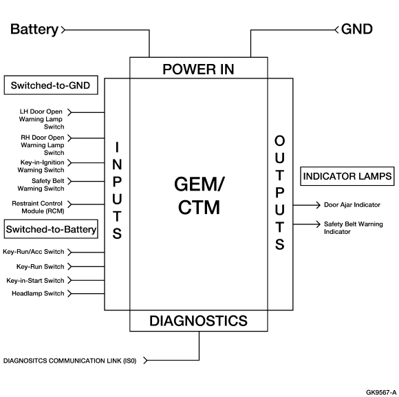
Ford GEM/CTM Module Block Diagram - Inputs, Outputs & Warning Indicators
Reference · 2005-2014 MustangAll 41 wiring diagrams
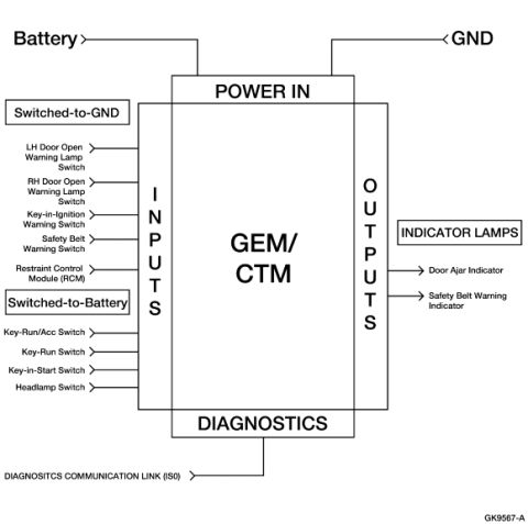









Wiring block diagram of the GEM/CTM module showing power-in, switched inputs, indicator-lamp outputs and the diagnostic communication link.
Part of 2005-2014 Ford Mustang Wiring Diagrams
This document is a block diagram illustrating the input/output architecture of a Ford GEM/CTM (Generic Electronic Module / Central Timer Module). The module is shown at center with Power In connections from Battery and GND at the top. On the left side, inputs are divided into two categories: Switched-to-GND inputs, which include the LH Door Open Warning Lamp Switch, RH Door Open Warning Lamp Switch, Key-in-Ignition Warning Switch, Safety Belt Warning Switch, and Restraint Control Module (RCM); and Switched-to-Battery inputs, which include the Key-Run/Acc Switch, Key-Run Switch, Key-in-Start Switch, and Headlamp Switch. On the right side, outputs drive indicator lamps: the Door Ajar Indicator and the Safety Belt Warning Indicator. At the bottom, a Diagnostics block connects to a diagnostics communication link (labeled 'DIAGNOSITCS COMMUNICATION LINK (IS0)', likely a typo for ISO). The diagram reference code GK9567-A appears in the lower right corner. A reader can learn which switches and modules feed the GEM/CTM, how they are grouped by switching type, and which warning indicators the module controls. No wire colors, connector pins, or fuse values are provided in this conceptual diagram.
Is this accurate? Sign in to help verify it.
Frequently asked questions
- What inputs does the Ford GEM/CTM module receive?
- Switched-to-GND inputs: LH and RH Door Open Warning Lamp Switches, Key-in-Ignition Warning Switch, Safety Belt Warning Switch, and the Restraint Control Module (RCM). Switched-to-Battery inputs: Key-Run/Acc Switch, Key-Run Switch, Key-in-Start Switch, and Headlamp Switch.
- What outputs does the GEM/CTM control according to this diagram?
- The GEM/CTM outputs drive indicator lamps: the Door Ajar Indicator and the Safety Belt Warning Indicator.
- How is the GEM/CTM powered in this diagram?
- Power In connections come from the Battery and GND at the top of the module.
- Does the GEM/CTM have a diagnostics connection?
- Yes, a Diagnostics block at the bottom of the module connects to a diagnostics communication link (labeled 'DIAGNOSITCS COMMUNICATION LINK (IS0)').
- What is the diagram reference number?
- The diagram is labeled GK9567-A in the lower right corner.






No comments yet.