Home/
Registry/
Ford/
Mustang/
2005-2014/
“SHELBY GT500”/
Photo
supermotors.net/registry/media/655665
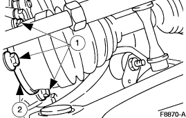
Ford Service Illustration F8870-A - Hub/Axle Component Callout Diagram

Reference · 2005-2014 MustangAll 52 service procedures
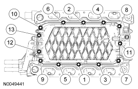
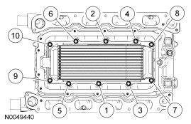
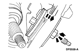
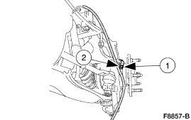
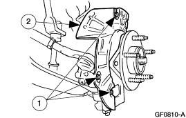
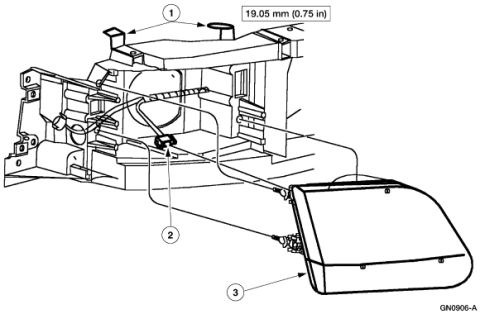
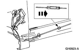









Service illustration of a mechanical assembly close-up with directional arrows and numbered callouts indicating removal steps.
Part of 2005-2014 Ford Mustang Service Procedures
This document is a single black-and-white line-art service illustration bearing the Ford figure reference code F8870-A. It shows an underbody/front-axle area component assembly, consistent with a hub, axle, or drivetrain-related service procedure based on the upload filename ('hub4.gif'), with two numbered callouts. Callout (1) points with arrows toward the upper/central portion of the assembly, appearing to indicate fasteners or attachment points on a large boot- or shaft-like component. Callout (2) points to a lower bracket or clamp area near the bottom of the illustration. No legend, part numbers, torque specifications, or descriptive text accompanies the callouts in this scan, so the reader must consult the adjoining service-manual page (this appears to be one page/figure from a multi-page set of Ford service documentation uploaded to the same album) to identify what items (1) and (2) represent. The only identifying text is the figure code F8870-A in the lower right corner. From this image alone, a reader can learn the physical location and orientation of the two called-out items relative to the surrounding assembly, but not their names, fastener sizes, or torque values.
Is this accurate? Sign in to help verify it.
Frequently asked questions
- What figure number is this Ford service illustration?
- The illustration is labeled F8870-A in the lower right corner.
- How many callouts are shown in this diagram?
- Two numbered callouts, (1) and (2), point to components of the assembly.
- Does this diagram include a legend identifying callouts 1 and 2?
- No. Only the callout numbers and the figure code F8870-A are visible; no legend, part names, or torque values appear in this scan.






No comments yet.