Home/
Registry/
Ford/
Mustang/
2005-2014/
“SHELBY GT500”/
Photo
supermotors.net/registry/media/655667
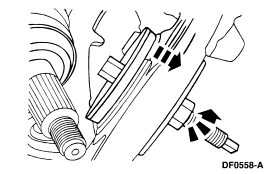
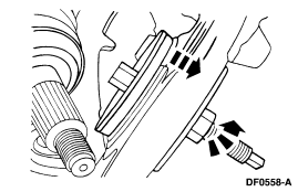
Ford Hub Service Procedure Illustration DF0558-A - Hub & Fastener Install Diagram
Reference · 2005-2014 MustangAll 52 service procedures

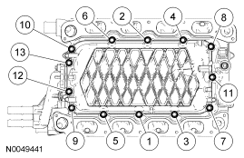
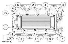
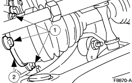
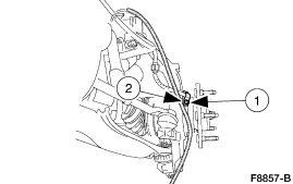
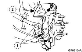
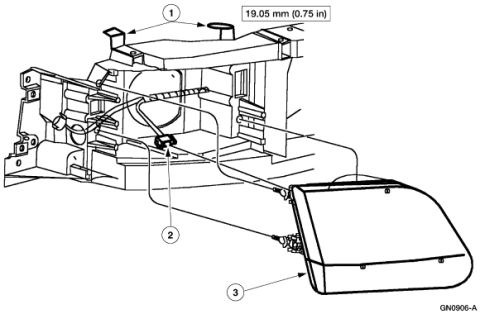









Service illustration of a mechanical component with directional arrows indicating a removal/installation motion.
Part of 2005-2014 Ford Mustang Service Procedures
This document is a single line-art service illustration (figure reference DF0558-A) from a Ford factory service procedure. The image shows a close-up exploded/installation view of what appears to be a wheel hub or brake area: a splined shaft (likely an axle or CV shaft) at the left, a large circular flanged component (such as a rotor shield, hub, or seal area) in the center, and a threaded fastener or stud with a hex head at the lower right. Two bold black arrows and a dashed arrow indicate the direction of installation or removal of the components. No captions, callout numbers, torque specifications, part numbers (other than the figure ID), or vehicle applicability information is printed on the illustration itself. The only text visible is the Ford illustration identifier 'DF0558-A' in the lower right corner. Because the figure carries no year, model, or engine markings, its exact application cannot be determined from the image alone; it was uploaded as part of a multi-page set of service diagrams (filename 'hub6.gif'), suggesting it is one step in a hub or wheel bearing service procedure. Readers can learn the general orientation and direction of assembly for the depicted components but must consult the accompanying procedure text for details.
Is this accurate? Sign in to help verify it.
Frequently asked questions
- What does this diagram show?
- It is a line-art service illustration showing a splined shaft, a circular hub/flange component, and a threaded fastener, with arrows indicating the direction of installation or removal.
- Is there a figure or reference number on this illustration?
- Yes, the illustration is identified as DF0558-A in the lower right corner.
- Does the diagram include torque specifications or part numbers?
- No. The only text visible on the illustration is the figure identifier DF0558-A; no torque values, part numbers, or captions appear.
- What do the arrows in the diagram indicate?
- The bold and dashed arrows indicate the direction in which the components (the hub/flange piece and the fastener) are installed or removed.






No comments yet.