Home/
Registry/
Ford/
Mustang/
2005-2014/
“SHELBY GT500”/
Photo
supermotors.net/registry/media/942867
2007 Ford Mustang Supercharger Intercooler Diagram - Callout Locations N0049440

Reference · 2005-2014 MustangAll 52 service procedures

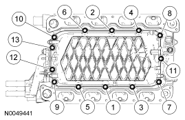
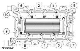









Torque-sequence diagram showing the numbered bolt tightening order for an intercooler or manifold cover.
Part of 2005-2014 Ford Mustang Service Procedures
This document is a single exploded/callout illustration (Ford figure number N0049440) showing a rectangular finned core, consistent with an intercooler or charge air cooler, seated inside a larger housing, likely a supercharger or intake assembly. Ten numbered callouts (1 through 10) point to fastener and component locations around the perimeter of the core and housing: callouts 2, 4, 6, and 8 along the top edge, callouts 1, 3, 5, and 7 along the bottom edge, and callouts 9 and 10 on the left side. The image contains no accompanying legend, part numbers, torque specifications, or descriptive text, so the specific identity of each numbered item cannot be determined from this page alone, it is evidently one page of a multi-page service procedure, where a separate legend or step list would define each callout. Uploaded to a 2007 Ford Mustang gallery with the filename "SC4.gif," it most plausibly relates to a supercharger intercooler installation or removal sequence (such as bolt locations or tightening sequence). A reader can learn the physical layout of the ten fastener/component positions on the assembly, but must consult the companion pages of the procedure for names, torque values, and step-by-step instructions.
Is this accurate? Sign in to help verify it.
Frequently asked questions
- How many callout points are shown in this diagram?
- Ten numbered callouts (1 through 10) are shown pointing to locations around the assembly.
- What is the Ford figure reference number for this illustration?
- The figure reference number shown in the lower-left corner is N0049440.
- Where are the callouts positioned on the assembly?
- Callouts 2, 4, 6, and 8 are along the top edge, callouts 1, 3, 5, and 7 are along the bottom edge, and callouts 9 and 10 are on the left side of the assembly.
- Does this page include torque specs or a legend identifying each callout?
- No. The image contains only the numbered callouts and the figure number N0049440; there is no legend, torque values, or part numbers visible.






No comments yet.