Home/
Registry/
Ford/
Mustang/
2005-2014/
“SHELBY GT500”/
Photo
supermotors.net/registry/media/659689
Ford Manual HVAC Airflow & Control Knob Diagram (A/C Heater Schematic A0014472)

Reference · 2005-2014 MustangAll 19 schematics
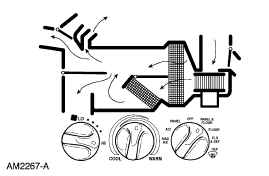
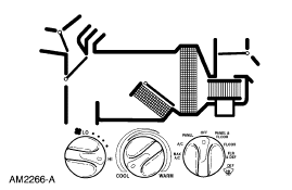
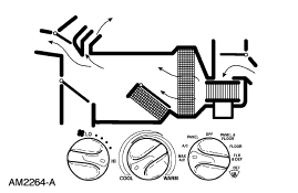
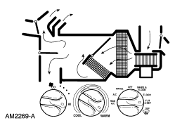
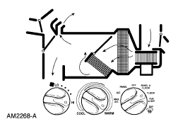
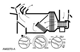
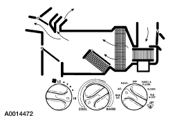









Schematic of HVAC airflow routing through the heater/AC case and ducts with control-knob settings.
Part of 2005-2014 Ford Mustang Schematics
This document is a Ford HVAC (heating, ventilation, and air conditioning) reference schematic identified by figure number A0014472. The upper portion is a pictorial cutaway of the climate-control air distribution system, using arrows to illustrate how air flows into and out of the HVAC plenum, through the fresh-air inlet, evaporator/heater core area, and out the defroster, instrument-panel, and floor outlets. The lower portion depicts the three rotary knobs of the manual climate control head: a blower speed knob marked from LO to HI, a temperature knob marked COOL to WARM, and a mode selector knob with positions including PANEL, PANEL & FLOOR, FLOOR, FLR & DEF, DEF, OFF, and MAX A/C. The document contains very little text beyond the knob position labels and the figure number; its value is chiefly visual, helping a reader understand which duct outlets correspond to each mode-knob position and how the manual HVAC controls relate to airflow paths. It was uploaded to a 2007 Ford Mustang gallery, though the graphic itself states no year, model, or engine applicability. It appears alongside other Ford factory-style illustrations (F-150-related diagrams) in the same album, so applicability to the claimed vehicle cannot be confirmed or denied from the document alone.
Is this accurate? Sign in to help verify it.
Frequently asked questions
- What are the positions on the HVAC mode selector knob shown in this diagram?
- The mode knob shows PANEL, PANEL & FLOOR, FLOOR, FLR & DEF, DEF, OFF, and MAX A/C positions.
- What do the other two knobs on the control panel adjust?
- One knob is the blower speed control, marked from LO to HI, and the other is the temperature control, marked COOL to WARM.
- What does the upper part of the diagram show?
- It is a pictorial airflow schematic of the HVAC air distribution system, with arrows showing air entering the system and exiting through the defroster, panel, and floor outlets.
- Is there a figure or reference number on this document?
- Yes, the diagram carries the identifier A0014472.






No comments yet.