Home/
Registry/
Ford/
Mustang/
2005-2014/
“SHELBY GT500”/
Photo
supermotors.net/registry/media/663995
Ford Transfer Case Component Diagram - Exploded View w/ Shift Motor (C11558-B)
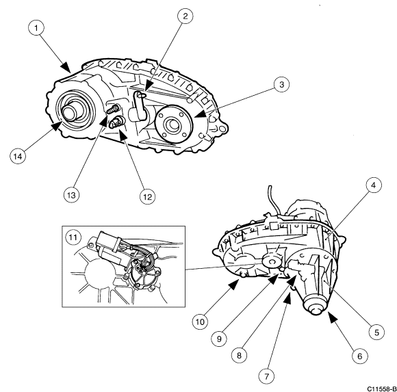
Transfer case component breakdown drawing with numbered callouts identifying housing and internal assembly parts.
Part of 2005-2014 Ford Mustang Exploded Parts Diagrams
This document is a black-and-white exploded/component identification illustration of a Ford transfer case assembly, identified by figure code C11558-B. It shows two main views of the transfer case: an upper view of the front/input side with callouts 1, 2, 3, 12, 13, and 14 pointing to features such as the case housing, input area components, and the front output/seal area, and a lower view of the rear/output side with callouts 4 through 10 indicating features around the rear output shaft, housing bolts, and sensor/plug locations. An inset box labeled with callout 11 shows a detail view of the electric shift motor/actuator mounted to the case. No legend or parts table accompanies the illustration in this scan, so the numbered items are not identified by name, and no part numbers, torque specifications, or fluid capacities are given. The drawing is useful for visually locating and identifying external transfer case components and their approximate positions on the housing, and would normally be paired with a numbered legend from a Ford workshop manual. The scan is clean and the callout numbers are fully legible.
Is this accurate? Sign in to help verify it.
Frequently asked questions
- What does this diagram show?
- It shows two views of a Ford transfer case assembly with numbered callouts 1 through 14 identifying external components, plus an inset detail (callout 11) of the electric shift motor/actuator.
- Does the diagram include a parts legend or part numbers?
- No. Only the numbered callout balloons (1-14) and the figure reference code C11558-B are visible; no legend, part names, or part numbers appear in this scan.
- What is the figure reference code on this illustration?
- The code printed at the bottom right of the illustration is C11558-B.
- How many components are called out in the diagram?
- Fourteen numbered callouts (1 through 14) are shown, with callout 11 identifying an inset detail view of the shift motor assembly.
Comments
More from this build














No comments yet.