Home/
Registry/
Ford/
Mustang/
2005-2014/
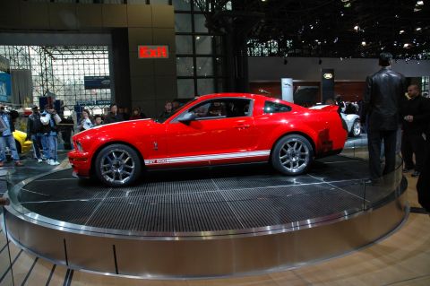
“SHELBY GT500”/
Photo
supermotors.net/registry/media/667116
Ford 4x4 Shift Motor Electrical Connector Diagram - Service Illustration C11698-A

Reference · 2005-2014 MustangAll 52 service procedures
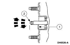
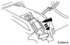
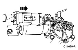
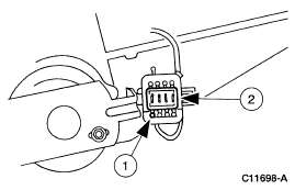
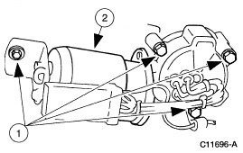
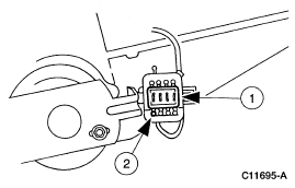
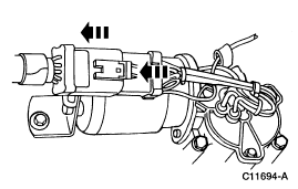
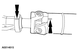
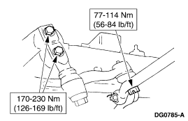
Service procedure figure identifying an electrical connector and its locking tab with numbered callouts.
Part of 2005-2014 Ford Mustang Service Procedures
This document is a single service-procedure illustration (Ford figure number C11698-A) showing an electrical connector and its mating component, marked with two numbered callouts (1 and 2). The drawing depicts a multi-pin connector being disconnected from or connected to a component mounted on what appears to be a transfer case or motor housing near a driveshaft yoke. Callout 1 points to the connector/component on the housing and callout 2 points to the harness-side connector. Based on the uploader's filename ('shift motor 5.gif'), this illustration appears to be one page of a multi-page procedure covering a 4x4 transfer case shift motor, showing the step where the shift motor electrical connector is disconnected or reconnected. The illustration contains no text legend, part numbers, torque specifications, wire colors, or year/model applicability information, only the two callout numbers and the Ford illustration reference code C11698-A. Readers can learn the location and orientation of the shift motor electrical connector relative to the component housing, which is useful when removing or installing the shift motor during service.
Is this accurate? Sign in to help verify it.
Frequently asked questions
- What does this illustration show?
- It shows an electrical connector (callout 2) and the component/connector it mates to (callout 1) on a housing near a driveshaft yoke, from a service procedure.
- What is the figure reference number for this illustration?
- The Ford illustration code shown is C11698-A.
- Does the document include torque specs or part numbers?
- No. The illustration contains only the numbered callouts 1 and 2 and the figure code C11698-A; no torque values, part numbers, or wire colors are shown.
- What year or model does this diagram apply to?
- The document itself gives no year, model, or engine applicability information.
No comments yet.