Home/
Registry/
Ford/
Mustang/
2005-2014/
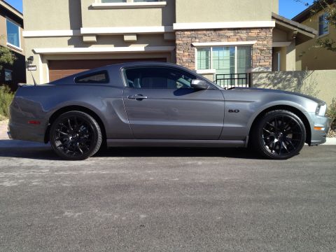
“SHELBY GT500”/
Photo
supermotors.net/registry/media/667117
Ford Shift Motor Removal Illustration C11699-A - Connector & Mounting Bolts

Service procedure figure showing connector removal with a directional arrow on an engine-mounted component.
This document is a black-and-white line-art service illustration, identified only by the Ford illustration reference number C11699-A. It depicts a motor assembly — per the uploader's filename, a transfer case shift motor — shown with its wiring harness and electrical connector at the upper left (an arrow indicates the direction of connector removal or installation), and what appears to be the motor housing mounted to a case flange at the right, with three circular callout bubbles pointing to fasteners or mounting bolts around the flange. The callout bubbles themselves are too small to read any numbers within them. No part numbers, torque specifications, step text, or captions appear in the image other than the illustration code. The drawing is typical of a factory workshop-manual figure used within a removal/installation procedure, showing where to disconnect the harness connector and which bolts to remove to detach the motor. Because the figure carries no year, model, or system labeling, a reader can learn only the general component orientation, the connector location, and approximate fastener positions; the accompanying procedure text (not present in this scan) would be needed for torque values and step-by-step instructions.
Is this accurate? Sign in to help verify it.
Frequently asked questions
- What does this diagram show?
- It is a service illustration (Ford figure C11699-A) of a motor assembly — labeled by the uploader as a shift motor — showing its electrical connector with an arrow indicating disconnect direction, and callouts pointing to mounting fasteners on the flange.
- Does the diagram include torque specs or part numbers?
- No. The only text visible in the image is the illustration reference number C11699-A; no torque values, part numbers, or step instructions are shown.
- Where is the electrical connector on this motor?
- The connector and wiring harness are shown at the upper-left of the motor assembly, with an arrow indicating the direction for disconnecting it.
- How many fastener callouts are shown?
- Three circular callout bubbles point to fastener locations around the mounting flange, though the numbers inside them are not legible.
Comments
More from this build













No comments yet.