Home/
Registry/
Ford/
Mustang/
2005-2014/
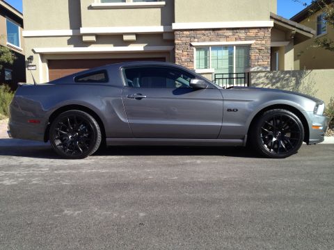
“SHELBY GT500”/
Photo
supermotors.net/registry/media/669315
Ford RABS Sensor Location & Removal Illustration E10054-A - Service Diagram
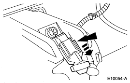
Service-manual line illustration (E10054-A) with callout arrows indicating a connector or component on a vehicle assembly.
This document is a single black-and-white line-art service illustration, identified by the Ford illustration reference number E10054-A. It depicts a component—based on the upload filename, related to the RABS (Rear Antilock Brake System)—mounted in a chassis/frame area, likely near an axle or differential housing. Two bold black arrows point to the component, indicating the direction of movement for removal or installation as part of a service procedure. A bolt or fastener head is visible near the mounting area, and wiring/harness routing is drawn above the component. The illustration contains no accompanying text, legend, torque specifications, part numbers, wire colors, or step-by-step instructions; it appears to be one figure extracted from a larger Ford factory service manual procedure. A reader can learn the approximate mounting location and orientation of the depicted component and the general direction of service action indicated by the arrows, but would need the surrounding manual text (not included in this scan) for fastener specs, connector details, and full procedure steps. The album context suggests this figure belongs to a set of Ford truck (F-150 era) service diagrams rather than the 2007 Mustang it is filed under.
Is this accurate? Sign in to help verify it.
Frequently asked questions
- What does this diagram show?
- It is a Ford service illustration (reference E10054-A) showing a chassis-mounted component with two arrows indicating the direction of removal or installation. Per the upload filename, it relates to the RABS (Rear Antilock Brake System).
- Does this document include torque specs or part numbers?
- No. The only text visible in the scan is the illustration reference number E10054-A; there are no torque values, part numbers, or written instructions.
- What do the black arrows in the illustration indicate?
- They point to the component and indicate the direction of movement for the service action (removal/installation) shown in the figure.
- Is a wiring harness shown in the illustration?
- Yes, a wiring/harness routing is drawn above the component, suggesting the part has an electrical connection.
Comments
More from this build






No comments yet.