Ford EEC-IV Self-Test Poor Ground Fix - Test Connector Jumper Wire Procedure

Reference · 1992-1996 BroncoAll 143 service procedures
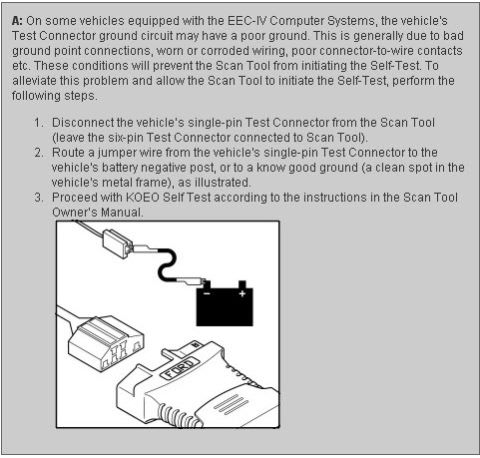
Step-by-step service procedure for re-grounding an EEC-IV scan tool single-pin test connector to the battery negative post to run a KOEO self-test.
Part of 1992-1996 Ford Bronco Service Procedures
This document is a troubleshooting note (formatted as an answer, "A:") addressing a common problem on Ford vehicles equipped with EEC-IV computer systems: a poor ground on the vehicle's Test Connector ground circuit, which prevents a Scan Tool from initiating the Self-Test. The document attributes the poor ground to bad ground point connections, worn or corroded wiring, or poor connector-to-wire contacts. It provides a three-step workaround: (1) disconnect the vehicle's single-pin Test Connector from the Scan Tool while leaving the six-pin Test Connector attached; (2) run a jumper wire from the single-pin Test Connector directly to the battery negative post or another known good ground, such as a clean spot on the vehicle's metal frame; and (3) proceed with the KOEO (Key On Engine Off) Self-Test per the Scan Tool Owner's Manual. An illustration shows the jumper wire routed from the single-pin connector to the battery negative terminal, with the six-pin diagnostic connector plugged into a Ford-branded scan tool. A reader learns how to bypass a faulty diagnostic ground so that self-test diagnostic codes can be retrieved. No specific years, models, or part numbers are stated in the document.
Is this accurate? Sign in to help verify it.
Frequently asked questions
- Why won't my Scan Tool initiate the EEC-IV Self-Test?
- The vehicle's Test Connector ground circuit may have a poor ground, generally caused by bad ground point connections, worn or corroded wiring, or poor connector-to-wire contacts. These conditions prevent the Scan Tool from initiating the Self-Test.
- How do I work around a poor ground on the EEC-IV Test Connector?
- Disconnect the vehicle's single-pin Test Connector from the Scan Tool (leaving the six-pin Test Connector connected), then route a jumper wire from the single-pin Test Connector to the battery negative post or a known good ground, such as a clean spot on the vehicle's metal frame.
- Do I disconnect both diagnostic connectors from the Scan Tool?
- No. Only disconnect the single-pin Test Connector; leave the six-pin Test Connector connected to the Scan Tool.
- What test do I run after installing the jumper wire?
- Proceed with the KOEO Self-Test according to the instructions in the Scan Tool Owner's Manual.
- What can I use as a ground point for the jumper wire?
- Either the vehicle's battery negative post or a known good ground, a clean spot on the vehicle's metal frame.




No comments yet.