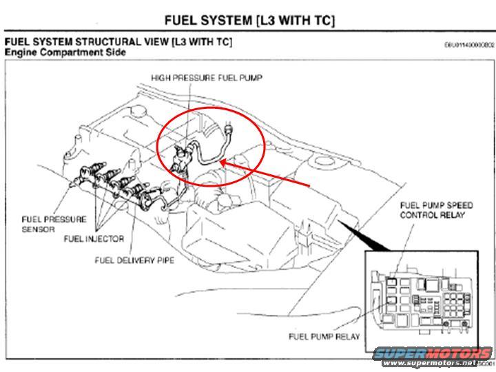
Mazda L3 Turbo (L3 with TC) Fuel System Diagram - High Pressure Fuel Pump & Relays
Reference · 1993-1997 ProbeAll 10 manual pages

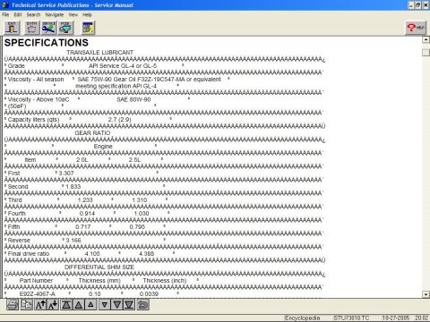
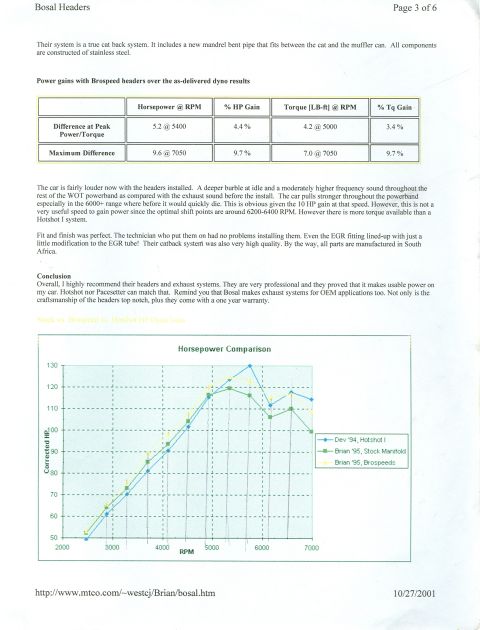


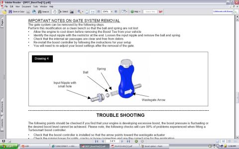
Service manual page showing the L3 turbo fuel system structural view with labeled pump, injectors, sensor and relays.
Part of 1993-1997 Ford Probe Manual Pages
This scanned service manual page is titled "FUEL SYSTEM [L3 WITH TC]" and presents the "Fuel System Structural View [L3 With TC], Engine Compartment Side." It is an illustrated diagram of the engine bay showing the physical locations of key fuel system components for the L3 turbocharged (TC) engine. Labeled components include the high pressure fuel pump (mounted atop the engine), the fuel pressure sensor, the fuel injectors, and the fuel delivery pipe (fuel rail) along the side of the engine. An inset detail drawing of the engine-compartment fuse/relay block identifies the positions of the fuel pump speed control relay and the fuel pump relay. A red circle and arrow have been added by the uploader to highlight the high pressure fuel pump's fuel hose connection. Document reference codes E6U011400000B02 and D6U114ZSC001 appear on the page. A reader can use this page to locate the high pressure fuel pump, its supply hose, the fuel rail components, and the two fuel pump relays in the fuse box for diagnosis or repair on an L3 turbo engine. No year, torque specs, or part numbers are given on the page.
Is this accurate? Sign in to help verify it.
Frequently asked questions
- Where is the high pressure fuel pump located on the L3 with TC engine?
- Per the structural view, the high pressure fuel pump is mounted on top of the engine in the engine compartment, with its fuel hose highlighted by the red circle and arrow in this scan.
- What fuel system components are shown in this diagram?
- The high pressure fuel pump, fuel pressure sensor, fuel injectors, fuel delivery pipe, fuel pump speed control relay, and fuel pump relay.
- Where are the fuel pump relay and fuel pump speed control relay located?
- Both are located in the engine-compartment fuse/relay box; the inset drawing at the lower right of the diagram points out their positions.
- What engine does this fuel system diagram apply to?
- The page states it applies to the L3 engine with TC (turbocharger), as titled "FUEL SYSTEM [L3 WITH TC]."

No comments yet.