Turbosmart Boost Tee Instructions - Gate System Removal & Troubleshooting

Reference · 1993-1997 ProbeAll 12 service procedures

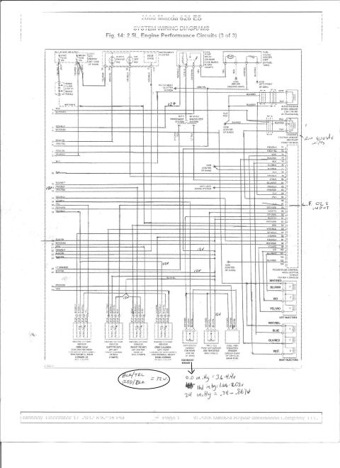
Service procedure page with step-by-step boost-tee gate removal instructions, a labeled figure and troubleshooting notes.
Part of 1993-1997 Ford Probe Service Procedures
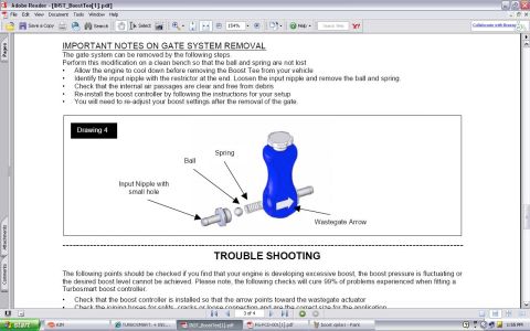
This document is page 3 of 4 of a Turbosmart Boost Tee manual boost controller instruction sheet (PDF filename INST_BoostTee[1].pdf, viewed in Adobe Reader). The visible section, titled 'Important Notes on Gate System Removal,' explains how to remove the gate system from the Boost Tee: work on a clean bench so the ball and spring are not lost, allow the engine to cool before removing the unit, identify and loosen the input nipple with the restrictor to remove the ball and spring, verify internal air passages are clear of debris, re-install the controller per the setup instructions, and re-adjust boost settings afterward. Drawing 4 shows an exploded view of the blue boost controller body with labeled components: the input nipple with a small hole, the ball, the spring, and the wastegate arrow indicating flow direction. Below this, a 'Trouble Shooting' section begins, addressing excessive boost, fluctuating boost pressure, or inability to reach the desired boost level; it states these checks cure 99% of problems when fitting a Turbosmart boost controller. The first two visible checks are ensuring the arrow points toward the wastegate actuator and inspecting joining hoses for splits, cracks, or loose connections and correct sizing. The page is cut off mid-list.
Is this accurate? Sign in to help verify it.
Frequently asked questions
- How do I remove the gate system from a Turbosmart Boost Tee?
- Work on a clean bench so the ball and spring aren't lost, let the engine cool before removing the Boost Tee, identify the input nipple with the restrictor at the end, loosen it, and remove the ball and spring. Then check the internal air passages are clear of debris, re-install the controller per your setup instructions, and re-adjust your boost settings.
- Do I need to re-adjust boost after removing the gate from the Boost Tee?
- Yes: the instructions state you will need to re-adjust your boost settings after removal of the gate.
- What should I check if boost is fluctuating or spiking with a Turbosmart boost controller?
- Check that the boost controller is installed with the arrow pointing toward the wastegate actuator, and check the joining hoses for splits, cracks, or loose connections and confirm they are the correct size for the application. The document says these checks cure 99% of fitment problems.
- Which direction should the arrow on the Boost Tee point?
- The arrow (labeled 'Wastegate Arrow' in Drawing 4) must point toward the wastegate actuator.
- What parts are inside the Boost Tee's gate system?
- Drawing 4 shows the input nipple with a small hole, a ball, and a spring that fit into the boost controller body.


No comments yet.