1995 Ford Probe Multi-Stage Boost Control Vacuum Routing Diagram - Wastegate Setup
Reference · 1993-1997 ProbeAll 9 vacuum routing diagrams
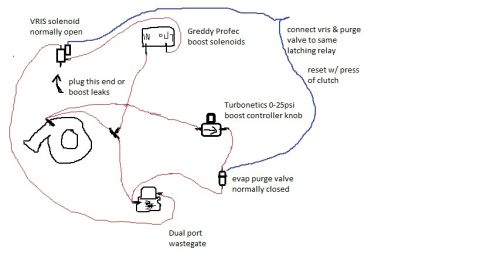
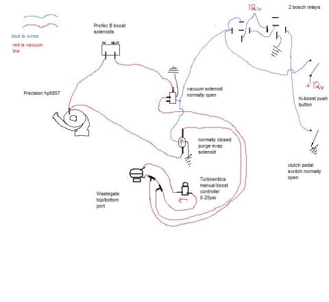
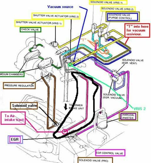
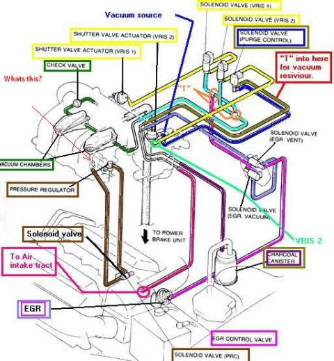
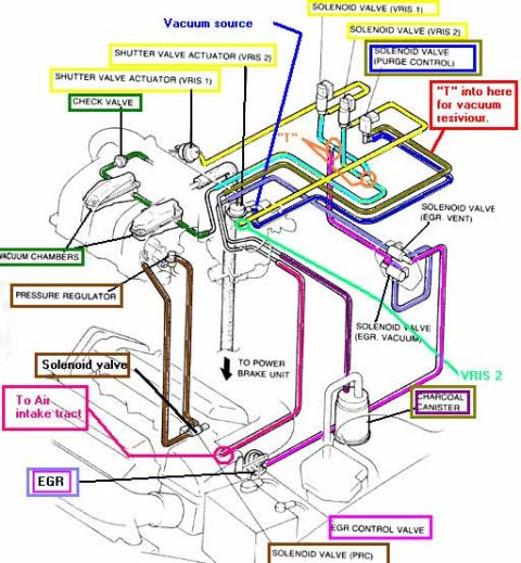
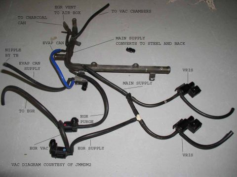
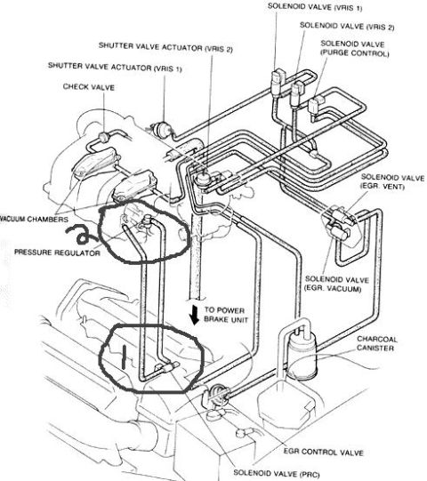
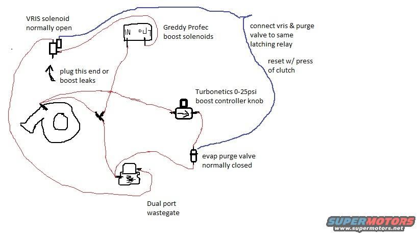
Hand-drawn vacuum routing for turbo boost control: VRIS solenoid (normally open), Greddy Profec boost solenoids, Turbonetics 0-25psi controller, evap purge valve (normally closed), dual-port wastegate.
Part of 1993-1997 Ford Probe Vacuum Routing Diagrams
This is a hand-drawn vacuum/pressure hose routing diagram uploaded as "multi stage boost.jpg," illustrating a custom multi-stage boost control setup on a turbocharged vehicle (claimed to be a 1995 Ford Probe). The sketch shows a turbocharger with a dual port wastegate connected via hose routing (red lines) to several components: a VRIS solenoid (noted as normally open), a Greddy Profec boost solenoid unit (with IN and OUT ports), a Turbonetics 0-25 psi manual boost controller knob, and an evap purge valve (noted as normally closed). Blue lines appear to indicate electrical wiring, with instructions to "connect vris & purge valve to same latching relay" and that the system is "reset w/ press of clutch." A note near the VRIS solenoid warns to "plug this end or boost leaks." The diagram documents how a repurposed VRIS solenoid and evap purge valve, controlled by a latching relay tied to the clutch pedal, work with a Greddy Profec electronic boost controller and Turbonetics manual controller to switch between boost levels feeding a dual port wastegate. No part numbers, years, or vehicle model identification appear in the document itself.
Is this accurate? Sign in to help verify it.
Frequently asked questions
- What boost controller is used in this multi-stage boost setup?
- A Greddy Profec electronic boost controller (boost solenoids) combined with a Turbonetics 0-25 psi manual boost controller knob.
- How are the VRIS solenoid and evap purge valve wired?
- The diagram says to connect the VRIS solenoid and purge valve to the same latching relay, which is reset with a press of the clutch.
- What are the default states of the solenoids in this setup?
- The VRIS solenoid is normally open and the evap purge valve is normally closed.
- What type of wastegate is shown in the diagram?
- A dual port wastegate connected to the turbocharger.
- What warning does the diagram give about the VRIS solenoid?
- It notes to "plug this end or boost leaks," referring to one port of the VRIS solenoid.




No comments yet.