Home/
Registry/
Ford/
LTD Crown Victoria/
1983-1991/
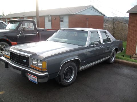
1985 Ford LTD Crown Victoria/
Photo
supermotors.net/registry/media/504704
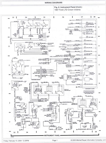
1987 Ford LTD Crown Victoria Instrument Panel Wiring Diagram (Cont.) - Fig. 6
.jpg)
Mitchell wiring diagram Fig. 6 for the 1987 Ford LTD Crown Victoria instrument panel, covering the cluster, warning lamps, auto A/C, blower/heater controls, wiper governor and clock circuits.
Part of 1983-1991 Ford LTD Crown Victoria Wiring Diagrams
This document is a scanned Mitchell Repair Information wiring diagram, labeled 'Fig. 6: Instrument Panel (Cont.)' for the 1987 Ford LTD Crown Victoria. It covers instrument-panel circuits across grid coordinates 23-28 (columns) and A-F (rows). Circuits shown include the interval wiper/washer switch with interval governor and wiper motor, the low washer fluid switch, rear window defogger switch with time delay, Tripminder module pinout (ignition power, dimmer, battery power, fuel flow input from ECA pin #34, speed input from cruise control amp, ground), instrument cluster warning indicators (brake, oil pressure, coolant temp, engine, hi-beam, turn signals, seat belt, low washer fluid, low fuel, alternator warning) with their connector pin numbers and wire colors, the fuel gauge and low fuel warning module, illumination lights (ashtray, A/C switch, clock, radio), and HVAC circuits, heater switch, auto and manual A/C function switches, blower motors, blower switches, blower resistors with thermal limiters, thermal blower lockout switch (opens below 120°F), A/C compressor clutch, clutch cycling pressure switch, A/C wide-open-throttle relay (EFI), and throttle kicker relay (carb). Fuse references (#2, #6, #8, #9, #13, #18) and full wire color codes are labeled throughout, plus the 18-pin instrument cluster connector layout. Footer shows a 2004 print date and 2003 Mitchell copyright.
This document covers 1987, which may differ from this 1985 Ford LTD Crown Victoria.
Is this accurate? Sign in to help verify it.
Frequently asked questions
- What fuse feeds the Tripminder module ignition power in the 1987 Crown Victoria?
- Ignition power at Tripminder pin 3 is a WHT-PPL wire fed from Fuse #6; battery power at pin 5 is LT GRN-YEL fed from Fuse #8.
- What wire color goes to the low fuel indicator on the instrument cluster?
- A YEL-BLK wire runs to cluster pin 6 for the LOW FUEL IND, driven by the low fuel warning module; the fuel gauge sender uses YEL-WHT wires.
- Which pins and wire colors handle the turn signal indicators?
- The right direction indicator is WHT-LT BLU at cluster pin 14 (multi-function switch pin #6), and the left direction indicator is LT GRN-WHT at pin 18 (multi-function switch pin #9).
- What does the thermal blower lockout switch do per this diagram?
- It is a normally closed switch in the blower circuit that opens below 120°F, wired with DK BLU-LT GRN and ORG wires.
- Which ECA pins connect to the A/C wide open throttle relay on EFI models?
- ECA pin #10 (PNK-LT BLU), pin #54 (ORG-LT BLU), and pin #37 (RED) connect to the A/C wide open throttle relay (EFI).
Comments
More from this build









No comments yet.