SuperMotors SuperMotors SUPERMOTORS Search: try “orange Bronco on 35s”
Home/ Registry/ Ford/ Bronco/ 1992-1996/ “1995 Bronco”/ Photo supermotors.net/registry/media/830788

Ford Bronco Radius Arm C-Bracket Dimensions - CAD Blueprint with Hole Locations

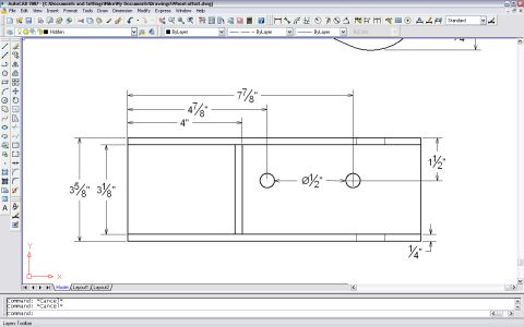
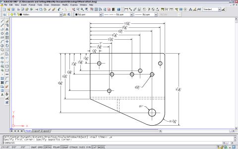
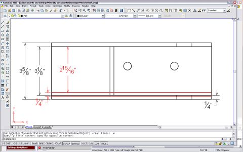
AutoCAD dimensioned drawing of a wheel offset bracket profile with bolt holes
AutoCAD dimensioned drawing of a wheel offset bracket profile with bolt holesOriginal file
AutoCAD dimensioned drawing of a wheel offset bracket profile with bolt holes

Reference · 1992-1996 BroncoAll 81 blueprints
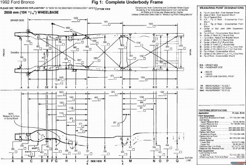
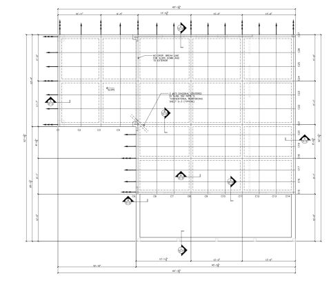
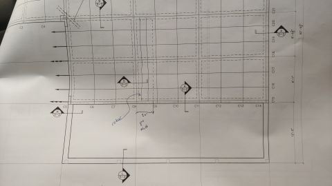
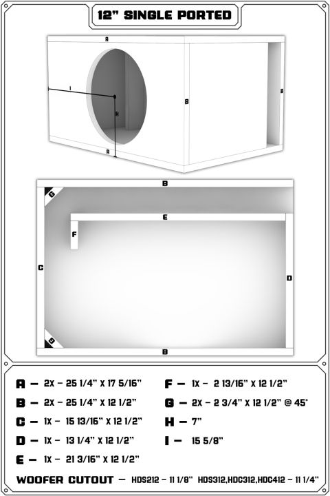
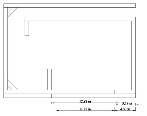
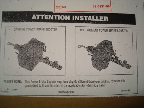
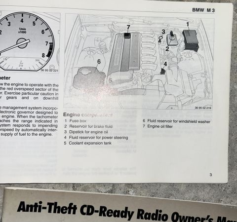
1992 Ford Bronco complete underbody frame dimensions, top and side views with 2659 mm (104 11/16 in) wheelbase 1995 Ford Bronco Outer Ring Blueprint - Dimensions & Bolt Hole Circle Diagram DIY Beadlock Inner Ring Blueprint - Dimensions & Bolt Hole Circle Specs 1995 Ford Bronco Radius Arm Frame Mount Bracket Blueprint - Dimensions Drawing Ford Bronco Radius Arm Frame Mount Bracket Blueprint - Hole Dimensions (CAD) 1995 Ford Bronco Bracket Blueprint - Wheel Offset Drawing Dimensions (AutoCAD) Ford Bronco Radius Arm C-Bracket Dimensions - CAD Blueprint with Hole Locations Brake Booster to Master Cylinder Adapter Plate Blueprint - Ford Bronco Swap Shop Foundation Slab Plan Blueprint - 60' x 52' Layout with Section Details S-2 Shop Foundation Plan Drawing - Grid C3-C21, S-2 Section Callouts & Dimensions 12" Single Ported Subwoofer Box Cut Sheet & Blueprint (HDS/HDC 12" Subs) 1994 Ford Bronco Custom Sub Box Top View Blueprint - Dimensions & Layout 81blueprints1992-1996 Ford Bronco More reference Remanufactured Power Brake Booster Installer Notice 91-0831-99 - Ford BroncoService procedure Ford Bronco Pinion Angle Diagram - Drive Shaft & Pinion Flange AnglesSchematic 1996 Ford Bronco C202F 76-Pin Connector Pinout - EVTM Page 150-4Wiring diagram 1996 Ford Bronco/F-150 Distributor Exploded Parts Diagram & Installation 03-07A-6Exploded parts 1994 Ford Bronco Door Data Spec Plate - VIN, GVWR, Axle & Paint CodesSpec plate BMW M3 Owner's Manual Page 3 - Engine Compartment Component LocationsManual page 1994-1995 BMW 3 Series Owner's Manual Booklet Set - Warranty, Radio & AccessoriesBrochure 1995 Ford Bronco 5.8L Emissions/VECI Label - Vacuum Hose Routing DiagramVacuum routing Ford Bronco/F-Series Fuse 18 (10A) - Speedometer, Air Bag, Shift ControlFuse chart Rod Bolt Stretch Monitoring Chart - 8-Rod V8 Connecting Rod Bolt Record SheetTorque spec

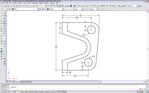
Dimensioned AutoCAD blueprint of a bracket profile showing hole diameters and overall measurements.

Part of 1992-1996 Ford Bronco Blueprints

AI caption · Photo 474 of 657

This document is a screenshot of AutoCAD 2007 showing a fully dimensioned 2D blueprint of a bracket-shaped part (file name "Wheel offset.dwg," uploaded to the vehicle album as "RA C Dims.jpg," suggesting it depicts radius arm C-bracket dimensions). The part is a roughly rectangular plate with a large U-shaped cutout on the left side, a rounded lower-right corner, and two 1 1/4" diameter holes. Key dimensions shown: overall width 5 3/4" and overall height 7 7/16"; the upper hole center is located 4 9/16" from the left edge and 1 1/8" down from the top edge; the lower hole center is 4 1/16" from the left edge and 1 3/16" up from the bottom edge. Additional dimensions include a 1 3/4" vertical measurement at the upper left and a 13/16" horizontal measurement at the lower left, defining the cutout geometry. A reader can use this drawing to fabricate or verify the dimensions of this bracket, likely a Ford radius arm frame-mount "C" bracket, given the companion files in the album (Radius Arm Frame Mounts, Bracket, Pinion Angle). No year, model, part number, or material specification appears in the drawing itself.

Is this accurate? Sign in to help verify it.

Frequently asked questions

What are the overall dimensions of the bracket in this drawing?
The bracket is 5 3/4 inches wide at the top and 7 7/16 inches tall on the left side.
What size are the two holes in the bracket?
Both holes are 1 1/4 inch (Ø1 1/4") in diameter.
Where are the hole centers located?
The upper hole center is 4 9/16" from the left edge and 1 1/8" down from the top edge. The lower hole center is 4 1/16" from the left edge and 1 3/16" up from the bottom edge.
What software was used to create this drawing?
The drawing is shown in AutoCAD 2007, with the file saved as "Wheel offset.dwg."
Does the drawing specify material thickness or part numbers?
No. Only the 2D profile dimensions and hole sizes/locations are shown; no thickness, material, or part numbers appear.


Comments

No comments yet.

More 1992-1996 Broncos