Home/
Registry/
Ford/
Bronco/
1992-1996/
1995 Ford Bronco/
Photo
supermotors.net/registry/media/1167775
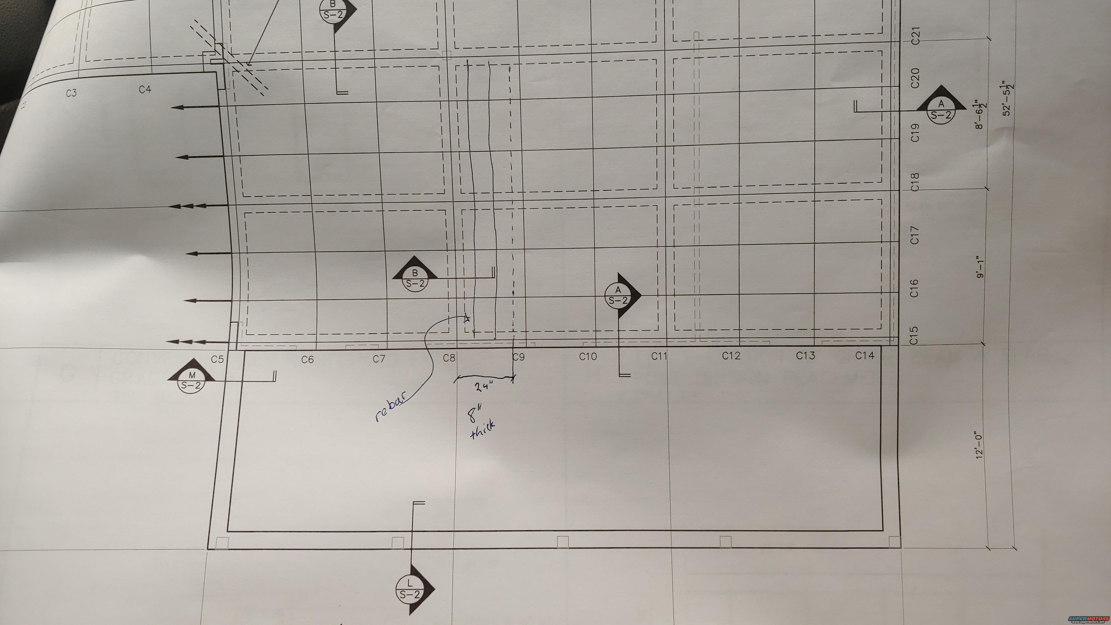
Shop Foundation Plan Drawing - Grid C3-C21, S-2 Section Callouts & Dimensions
Reference · 1992-1996 BroncoAll 81 blueprints
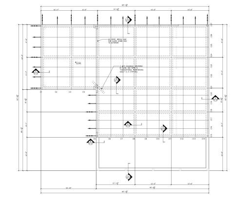
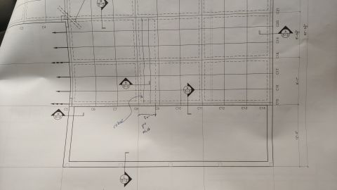


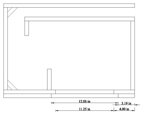
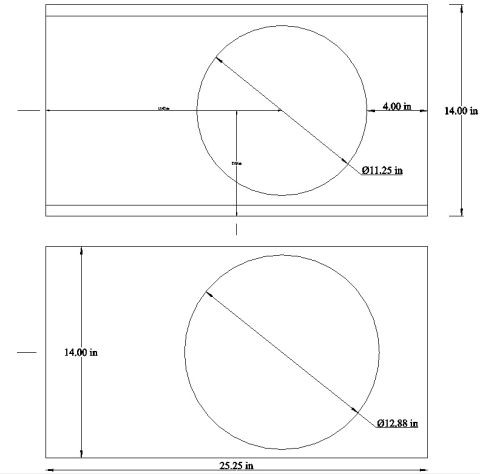
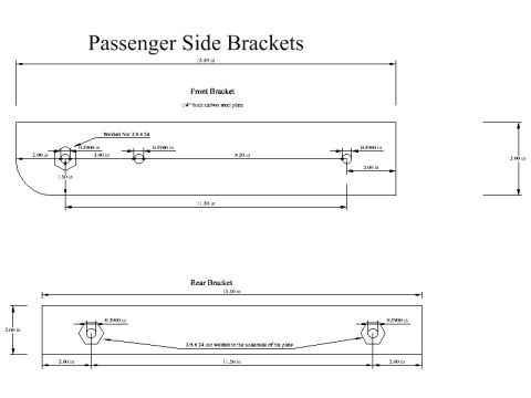
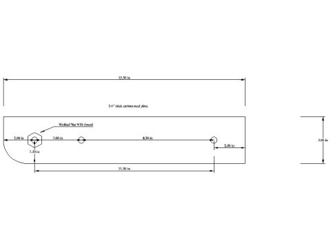
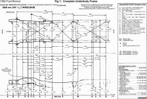
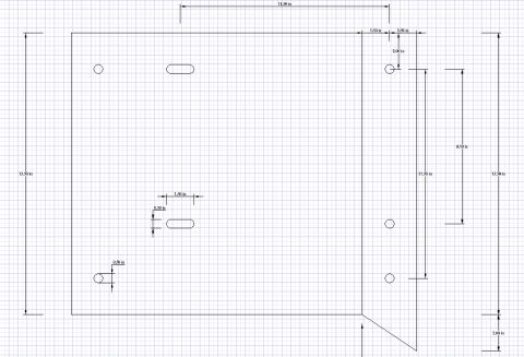



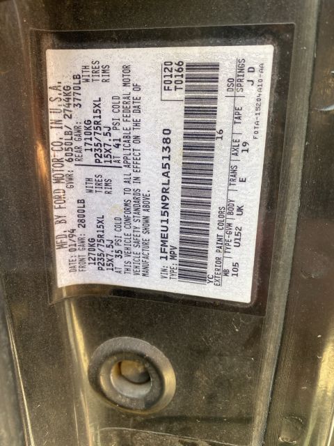




Structural foundation/slab plan showing a column grid (C1-C14), dimensions and detail callouts.
Part of 1992-1996 Ford Bronco Blueprints
This scan is a portion of an architectural/structural foundation plan drawing (site-labeled as part of a 'shop foundation drawing' set) that was uploaded to a 1995 Ford Bronco gallery, but it contains no automotive content. The sheet shows a plan view of a building foundation with a rectangular grid of column/gridline callouts labeled C3 through C21 running along the top, bottom, and right edges. Dashed lines indicate footings or grade beams beneath the slab grid. Several section cut markers reference details on sheet S-2, including sections A, B, L, and M. Overall dimensions are given along the right edge: 8'-6 1/2", 52'-5 1/2", 9'-1", and 12'-0", the last apparently for a lower rectangular slab or apron area spanning roughly gridlines C5 to C14. Handwritten field notes in ink mark a location near gridline C8 as 'rebar,' call out a 24" dimension between tick marks, and note the slab or wall there is '8" thick.' A reader can learn the grid layout, section references to sheet S-2, key overall dimensions, and the annotated rebar location and slab thickness. No title block, date, or vehicle applicability information is visible.
Is this accurate? Sign in to help verify it.
Frequently asked questions
- What sheet do the section callouts on this foundation plan reference?
- All visible section markers (A, B, L, and M) reference details on sheet S-2.
- What overall dimensions are shown on this foundation plan?
- Dimensions along the right edge include 8'-6 1/2", 52'-5 1/2", 9'-1", and 12'-0".
- What do the handwritten notes on the drawing indicate?
- Handwritten ink notes mark a 'rebar' location near gridline C8, a 24" dimension between tick marks, and an '8" thick' callout for the slab/wall in that area.
- How are the gridlines labeled on this plan?
- Column/gridlines are labeled C3 and C4 at top, C5 through C14 across the middle, and C15 through C21 along the right edge.






No comments yet.