Home/
Registry/
Ford/
Bronco/
1992-1996/
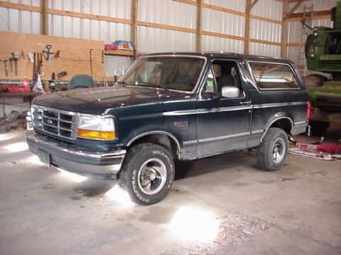
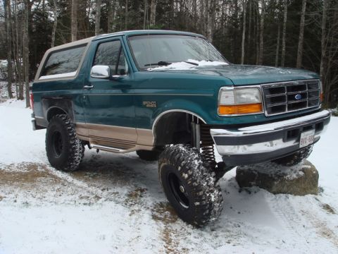
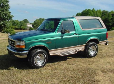
“1995 Bronco”/
Photo
supermotors.net/registry/media/1012033
Ford Bronco Pinion Angle Diagram - Drive Shaft & Pinion Flange Angles

Reference · 1992-1996 BroncoAll 95 schematics

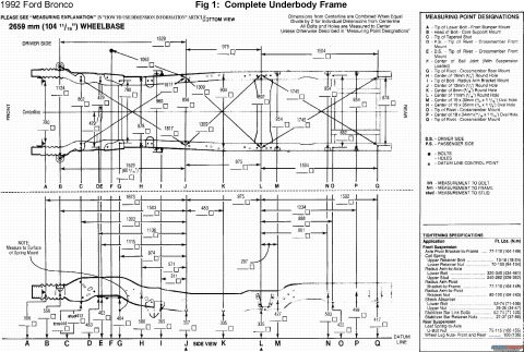
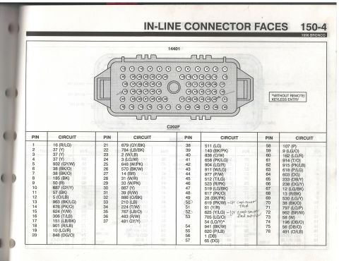
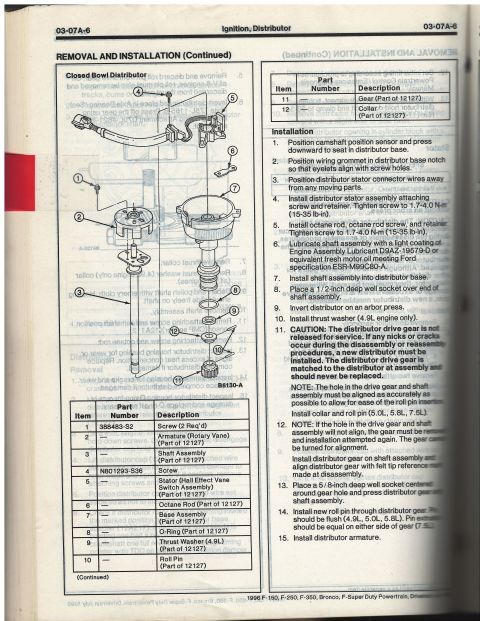
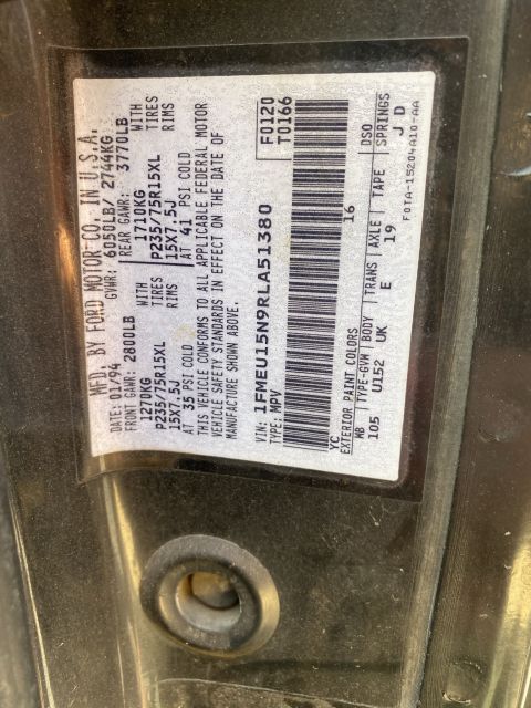


Schematic showing pinion flange and drive shaft angles to evaluate driveline operating angle.
Part of 1992-1996 Ford Bronco Schematics
This is a simple CAD-style annotated diagram illustrating driveline (pinion) angle geometry, uploaded to a 1995 Ford Bronco gallery. It shows two intersecting lines: one representing the pinion flange at 18 degrees, and one representing the drive shaft at 22 degrees. The included angle between the pinion flange line and the drive shaft line is dimensioned at 87 degrees, and a note explains: 'THIS ANGLE IS 3° FROM BEING PERPENDICULAR. SO IN MY THINKING I AM GOOD WHERE I AM.' The document appears to be the uploader's own working sketch used to evaluate whether their measured pinion angle relative to the drive shaft is acceptable, the reasoning being that a 90-degree (perpendicular) relationship would represent zero operating angle, and their measured 87 degrees puts them 3 degrees off perpendicular (i.e., roughly a 3-degree U-joint operating angle). A reader can learn the specific measured values (18° pinion flange, 22° drive shaft, 87° included angle) and the owner's conclusion that the current setup is acceptable. The diagram contains no part numbers, torque specs, or explicit vehicle/year identification; it is part of an album that also includes radius arm and bracket dimension drawings, suggesting a suspension lift or drivetrain modification project.
Is this accurate? Sign in to help verify it.
Frequently asked questions
- What pinion flange angle is shown in this diagram?
- The pinion flange is labeled at 18 degrees (shown as 18*).
- What is the drive shaft angle in this diagram?
- The drive shaft is labeled at 22 degrees (shown as 22*).
- What is the angle between the pinion flange and the drive shaft?
- The diagram dimensions the angle between the pinion flange line and the drive shaft at 87 degrees, which the note says is 3° from being perpendicular.
- Does the author consider this pinion angle acceptable?
- Yes. The note states: 'THIS ANGLE IS 3° FROM BEING PERPENDICULAR. SO IN MY THINKING I AM GOOD WHERE I AM.'

No comments yet.