1985-91 Ford Open-Bowl TFI Distributor Exploded Diagram - Rotor & Cap Details
Reference · 1987-1991 BroncoAll 61 exploded parts diagrams
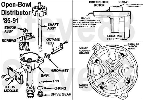








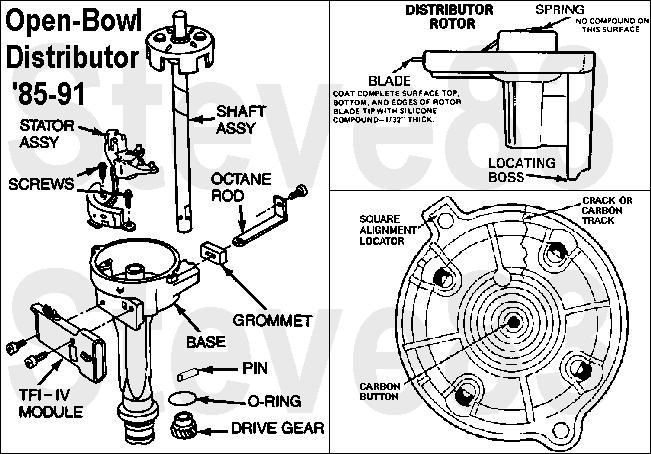
Exploded parts breakdown of an open-bowl distributor (1985-91) showing shaft, stator, TFI-IV module, rotor, and distributor cap components.
Part of 1987-1991 Ford Bronco Exploded Parts Diagrams
This document is an exploded parts diagram of the '85-91 open-bowl style Ford distributor, showing the disassembled components and their names: shaft assembly, stator assembly, screws, octane rod, grommet, base, pin, O-ring, TFI-IV module, and drive gear. A second panel illustrates the distributor rotor, labeling the spring, blade, and locating boss, with service notes stating that the complete surface top, bottom, and edges of the rotor blade tip should be coated with silicone compound 1/32" thick, and that no compound should be applied to the spring contact surface. A third panel shows the inside of the distributor cap, identifying the square alignment locator, carbon button, and areas to inspect for cracks or carbon tracking. A reader can learn the internal parts layout of the open-bowl TFI-IV distributor for reassembly or parts identification, the proper silicone dielectric compound application on the rotor blade, and what to inspect on the cap (cracks/carbon tracks) during ignition service. The diagram applies to 1985-1991 vehicles per its own title and is relevant to the uploader's 1990 Ford Bronco.
Is this accurate? Sign in to help verify it.
Frequently asked questions
- What years does this open-bowl distributor diagram cover?
- The document is titled 'Open-Bowl Distributor '85-91', so it covers 1985 through 1991.
- What parts make up the open-bowl distributor?
- The exploded view labels the shaft assembly, stator assembly, screws, octane rod, grommet, base, pin, O-ring, TFI-IV module, and drive gear.
- Where should silicone compound be applied on the distributor rotor?
- Coat the complete surface top, bottom, and edges of the rotor blade tip with silicone compound 1/32" thick, but apply no compound to the spring contact surface.
- What should be inspected on the distributor cap?
- The cap diagram calls out checking for cracks or carbon tracks, and identifies the carbon button and square alignment locator.
- What ignition module is used in this distributor?
- The diagram shows a TFI-IV module mounted on the distributor base.






No comments yet.