Home/
Registry/
Ford/
Bronco/
1992-1996/
“pukin' dogII”/
Photo
supermotors.net/registry/media/877847
1996 Ford Bronco 5.8L O2 Sensor Locations - Heated Oxygen & Catalyst Sensors

Reference · 1992-1996 BroncoAll 98 manual pages
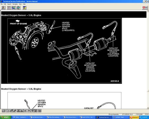
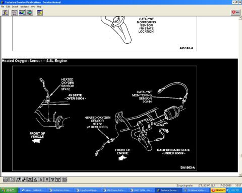








Service manual page illustrating heated oxygen and catalyst monitoring sensor locations on the 5.8L engine exhaust.
Part of 1992-1996 Ford Bronco Manual Pages
This is a screenshot of a page from Ford's Technical Service Publications service manual software showing heated oxygen sensor (HO2S) locations for the 5.8L engine. The main illustration (figure DA1663-A) depicts the exhaust system layout with callouts identifying the Heated Oxygen Sensor (part designation 9F472) and the Catalyst Monitoring Sensor (9G444). Two configurations are shown: the "49 STATE - OVER 8500#" (GVWR) application, which shows a single heated oxygen sensor location near the exhaust manifold, and the "CALIFORNIA/49 STATE - UNDER 8500#" application, which uses two heated oxygen sensors (9F472, "2 REQUIRED") upstream of the catalytic converters plus a catalyst monitoring sensor (9G444) downstream. Orientation arrows indicate "FRONT OF VEHICLE" and "FRONT OF ENGINE." A partial diagram at the top of the screen (figure A25143-A) shows the catalyst monitoring sensor 49-state location for a preceding section. A reader can learn where each oxygen sensor is physically mounted on the exhaust system of a 5.8L-equipped truck, how sensor count and placement differ between emissions calibrations (California vs. 49-state) and GVWR classes (over/under 8500 lb), and the Ford base part-number designations for the sensors. The file reference STJ3E041.GUI appears in the status bar; no model year is stated on the page itself.
Is this accurate? Sign in to help verify it.
Frequently asked questions
- Where are the oxygen sensors located on the 5.8L engine?
- Per the diagram (DA1663-A), the heated oxygen sensors (9F472) are mounted in the exhaust pipes ahead of the catalytic converters, and a catalyst monitoring sensor (9G444) is mounted downstream near the converters. On 49-state over-8500# GVWR vehicles a single heated oxygen sensor location near the exhaust manifold is shown.
- How many oxygen sensors does the California/49-state under-8500# 5.8L application use?
- It uses two heated oxygen sensors (9F472, labeled "2 REQUIRED") plus a catalyst monitoring sensor (9G444).
- What are the Ford part designations for the sensors shown?
- The heated oxygen sensor is 9F472 and the catalyst monitoring sensor is 9G444.
- Do 49-state trucks over 8500# GVWR have a different sensor setup?
- Yes. The diagram labels a separate "49 STATE - OVER 8500#" heated oxygen sensor (9F472) location, distinct from the California/49-state under-8500# setup that uses two heated oxygen sensors and a catalyst monitoring sensor.






No comments yet.