Home/
Registry/
Ford/
Bronco/
1992-1996/
“pukin' dogII”/
Photo
supermotors.net/registry/media/877848
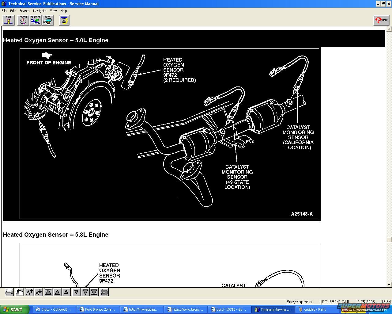
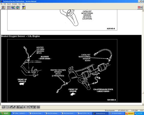
1996 Ford Bronco 5.0L & 5.8L Heated Oxygen Sensor (O2) Locations Diagram
Reference · 1992-1996 BroncoAll 98 manual pages
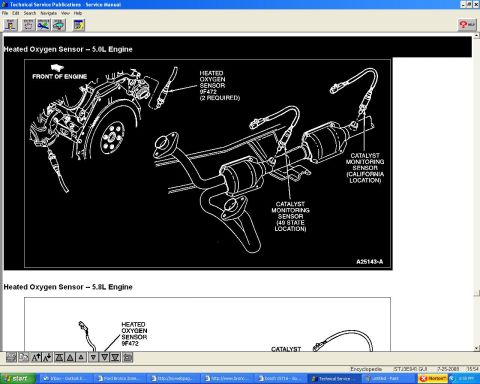

Service manual page illustrating heated oxygen and catalyst monitoring sensor locations on the 5.0L engine exhaust.
Part of 1992-1996 Ford Bronco Manual Pages
This document is a screenshot of a Ford Technical Service Publications (Service Manual) page showing the locations of the heated oxygen sensors on the 5.0L engine, with the beginning of a second diagram for the 5.8L engine visible at the bottom. The 5.0L diagram (figure reference A25143-A) is an exploded view of the exhaust system from the engine/bellhousing area rearward through the dual catalytic converters. It identifies the Heated Oxygen Sensor, Ford base part number 9F472, noting that 2 are required, mounted in the exhaust pipes upstream of the converters. It also shows two different locations for the catalyst monitoring sensor: one position labeled as the California location (further rearward on the passenger-side converter outlet) and another labeled the 49-state location (on the driver-side pipe after the converter). A 'FRONT OF ENGINE' arrow orients the view. The partially visible 5.8L engine diagram also calls out the Heated Oxygen Sensor 9F472 and begins a 'CATALYST' callout before being cut off by the screen edge. A reader can learn where the upstream O2 sensors and downstream catalyst monitor sensors are located, that emissions calibration (California vs. 49-state) changes the monitor sensor location, and the Ford part number group for the sensors.
Is this accurate? Sign in to help verify it.
Frequently asked questions
- How many heated oxygen sensors does the 5.0L engine use upstream?
- The diagram labels the heated oxygen sensor 9F472 as '2 REQUIRED', one in each exhaust pipe ahead of the catalytic converters.
- What is the Ford part number for the heated oxygen sensor?
- The diagram identifies the heated oxygen sensor as base part number 9F472.
- Where is the catalyst monitoring sensor located?
- The diagram shows two locations: a '49 STATE LOCATION' on one pipe after the converter and a 'CALIFORNIA LOCATION' on the other side, depending on the vehicle's emissions calibration.
- Does this document cover the 5.8L engine too?
- Yes, a second section titled 'Heated Oxygen Sensor -- 5.8L Engine' begins at the bottom of the page, also showing heated oxygen sensor 9F472, though the diagram is partially cut off in this screenshot.






No comments yet.