Ford Bronco 4WABS Anti-Lock Brake Wiring Diagram - Connector Pinouts C119 C121

Reference · 1980-1986 BroncoAll 92 wiring diagrams
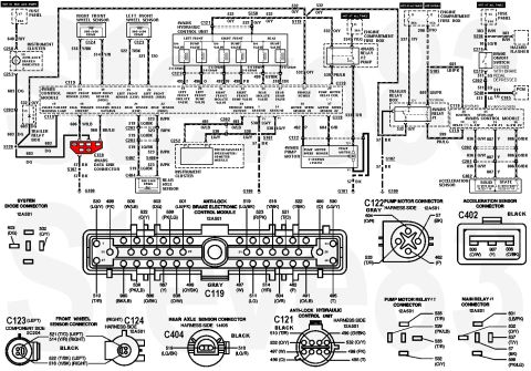
4WABS Circuit & Connectors
IF THE IMAGE IS TOO SMALL, click it.
'93 Bronco shown; '94-96 Bronco similar.
Front Wheel Speed Sensor Motorcraft BRAB30; Airtex ; Dorman 970-020; Standard ALS185; Motoneo F4TZ2C204A; Raybestos ABS530392; APDTY 081131
Rear axle ABS sensor (DY1123, F85Z-9E731-AB)
To bypass a suspected bad module, unplug the connector & install jumper wires: pin 1 (or 14; circuit 530 LG/Y) to 21 (519 LG/BK); pin 22 (523 R/Pk) to 39 (491 Or/LB). This shuts down ABS completely, but sends the ABS sensor signal directly to the PSOM for proper transmission (etc.) control.
 .
 .

Compare to:

For relay locations, see:

Part of 1980-1986 Ford Bronco Wiring Diagrams
Is this accurate? Sign in to help verify it.
Frequently asked questions
- What resistance should the 4WABS wheel speed sensors read?
- The right front, left front, and rear axle sensors are all specified at 800-1400 ohms on the diagram.
- What are the resistance specs for the hydraulic control unit valves?
- The iso valves are 5-8 ohms and the dump valves are 3-6 ohms per the diagram.
- What wire color is the 4WABS vehicle power circuit?
- Circuit 532, orange/yellow (O/Y), feeds vehicle power to pin 17 of the 4WABS control module, protected by 30A fuses in the engine compartment fuse box.
- Which connector is the 4WABS control module connector and what color is it?
- C119, a gray connector (part 12A581) with pins numbered up to 40, shown with full pinout including circuits like 530 LG/Y grounds at pins 1 and 14.
- What is the pump motor speed sensor specification?
- The pump motor speed sensor is listed as 5-40 ohms at ≥150 Hz, connected via circuits 462 (P) and 604 (O/R) at connector C122.
No comments yet.