1996 Ford Bronco Calibration 6-64T-R05 Vacuum Diagram & Emissions Parts List

Reference · 1992-1996 BroncoAll 40 vacuum routing diagrams

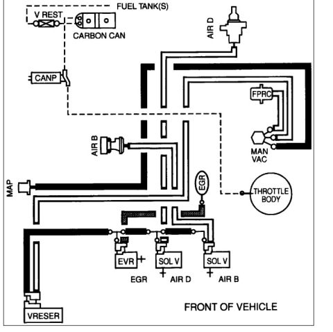
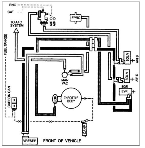
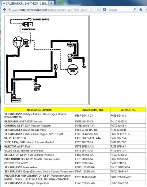
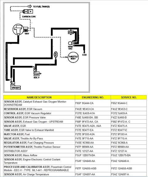

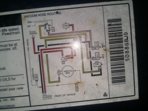
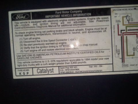

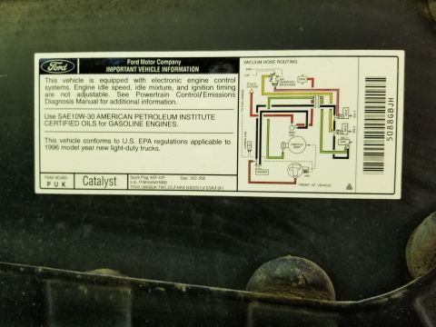
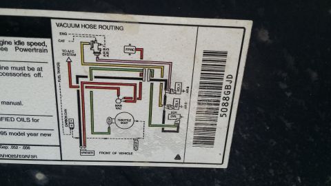
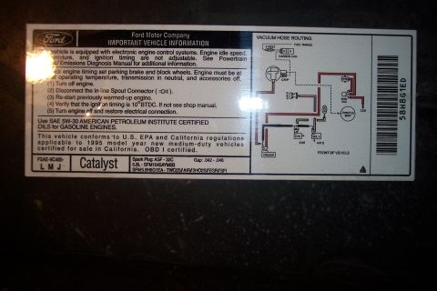










Motorcraft Service calibration 6-64T-R05 (1996) vacuum-routing schematic and parts list: EGR vacuum reservoir/regulator, EGR pressure valve, upstream/downstream HEGO, EEC-V ML1-441 PCM with engineering and service numbers.
Part of 1992-1996 Ford Bronco Vacuum Routing Diagrams
This document is a screenshot from the Motorcraft Service website (motorcraftservice.com) showing Ford emissions calibration 6-64T-R05 for a 1996 vehicle. It contains two parts: a vacuum routing schematic and a calibration parts list. The vacuum diagram shows hose routing between the carbon canister (with line to fuel tanks), vapor management valve (VMV), fuel pressure regulator control (FPRC), manifold vacuum (MAN VAC) source, throttle body, CCD, EGR solenoid valve (EGR SOL V), and vacuum reservoir (VRESER). The parts table lists sixteen emission-related components with both Ford Engineering and Service part numbers, including upstream and downstream oxygen sensors, EGR vacuum reservoir, EGR vacuum regulator control, EGR pressure valve sensor, EGR valve and tube, fuel injectors, throttle air bypass valve, fuel pressure regulator, throttle position sensor, distributor, mass airflow sensor, engine coolant temperature sensor, air charge temperature sensor, and the EEC-V powertrain control module (type ML1-441, reprogrammable, part F6TZ 12A650-ARB). This is useful for identifying correct replacement emissions parts and verifying vacuum hose routing for a vehicle carrying calibration code 6-64T-R05.
Is this accurate? Sign in to help verify it.
Frequently asked questions
- What calibration code does this document cover?
- Calibration 6-64T-R05, shown as a 1996 calibration on motorcraftservice.com.
- What is the service part number for the EEC-V powertrain control module?
- F6TZ 12A650-ARB (engineering number F6TF 12A650-ARB), type ML1-441, listed as reprogrammable.
- What are the part numbers for the oxygen sensors?
- Upstream exhaust gas oxygen sensor: engineering F68F 9F472-AA/CA, service F68Z 9F472-A/C. Downstream catalyst monitor sensor: engineering F65F 9G444-CA, service F65Z 9G444-C.
- What EGR components are listed?
- EGR vacuum reservoir (F4UZ 9E453-C), EGR vacuum regulator control (FOTZ 9J459-A), EGR pressure valve sensor (F4ZZ 9J460-B), EGR valve (F4TZ 9D475-A), and EGR valve to exhaust manifold tube (F5TZ 9D477-E).
- What components appear in the vacuum routing diagram?
- Carbon canister with line to fuel tank(s), VMV, FPRC, manifold vacuum (MAN VAC), CCD, throttle body, EGR solenoid valve, and a vacuum reservoir (VRESER).






No comments yet.