1994 Ford Bronco Vacuum Hose Routing Diagram - EGR, Thermactor Air, CANP, FPRC
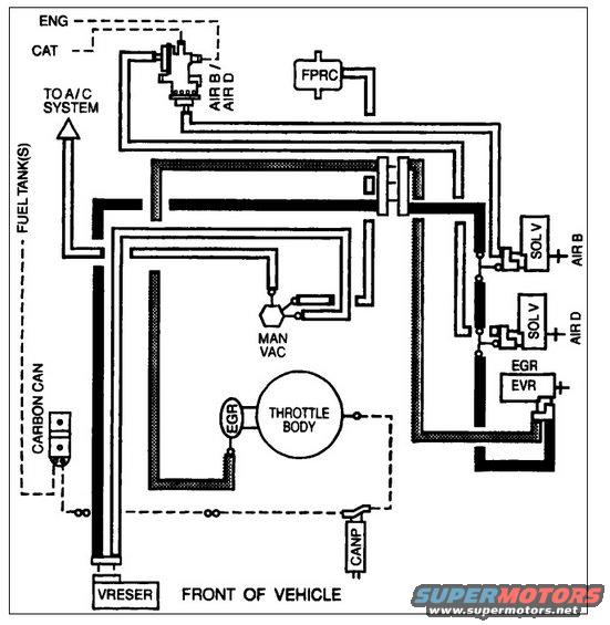
Vacuum routing diagram showing hose connections among the throttle body, EGR, air solenoids, FPRC, carbon canister and fuel tanks.
Part of 1992-1996 Ford Bronco Vacuum Routing Diagrams
This document is a vacuum hose routing schematic (typical of a Vehicle Emission Control Information / VECI diagram) showing the emissions and vacuum system layout as viewed with the front of the vehicle at the bottom. It depicts the routing of vacuum lines between major emission components: a fuel pressure regulator control (FPRC), an air-management valve directing air to AIR B (air bypass) and AIR D (air diverter) circuits with connections to the engine (ENG) and catalyst (CAT), two solenoid valves (SOL V) controlling AIR B and AIR D, the EGR valve mounted at the throttle body, an EGR vacuum regulator (EVR), a manifold vacuum (MAN VAC) source fitting, the carbon canister (CARBON CAN) with a line to the fuel tank(s), a canister purge solenoid (CANP), a vacuum reservoir (VRESER), and a takeoff to the A/C system. Solid heavy lines, hatched lines, and dashed lines distinguish different hose types/circuits. A reader can trace which component connects to which vacuum source, useful when replacing hoses or diagnosing vacuum leaks and emission control faults. The diagram contains no part numbers, calibration codes, or explicit year/engine identification on the visible image.
Is this accurate? Sign in to help verify it.
Frequently asked questions
- What components are shown on this vacuum routing diagram?
- It shows the FPRC, air bypass/diverter valve (AIR B / AIR D) with SOL V solenoids, EGR valve and EVR, throttle body, manifold vacuum (MAN VAC) fitting, carbon canister, CANP purge solenoid, vacuum reservoir (VRESER), and a line to the A/C system.
- Where does the carbon canister connect?
- The carbon canister (CARBON CAN) connects via a line labeled to the fuel tank(s) and through dashed lines toward the CANP (canister purge) solenoid near the throttle body.
- How is the EGR system controlled in this diagram?
- The EGR valve at the throttle body is connected to an EGR EVR (EGR vacuum regulator) on the right side of the diagram.
- What do the AIR B and AIR D labels mean on the solenoids?
- Two SOL V (solenoid valves) are labeled AIR B and AIR D, controlling the air valve that routes air to the engine (ENG) and catalyst (CAT) at the top of the diagram.
- How is the diagram oriented?
- The bottom of the diagram is labeled 'FRONT OF VEHICLE,' so the layout is viewed with the vehicle front at the bottom.
Comments
More from this build







No comments yet.