Home/
Registry/
Ford/
Bronco/
1992-1996/
1995 Ford Bronco/
Photo
supermotors.net/registry/media/975810
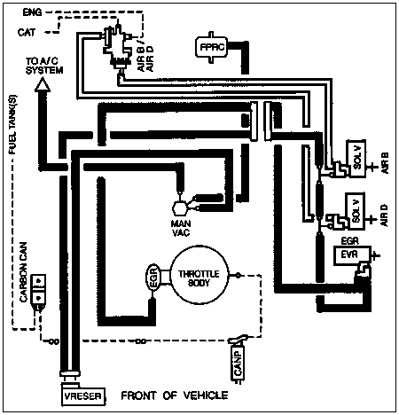
1995 Ford Bronco Vacuum Hose Routing Diagram - EGR, AIR, CANP, FPRC Lines
Reference · 1992-1996 BroncoAll 40 vacuum routing diagrams
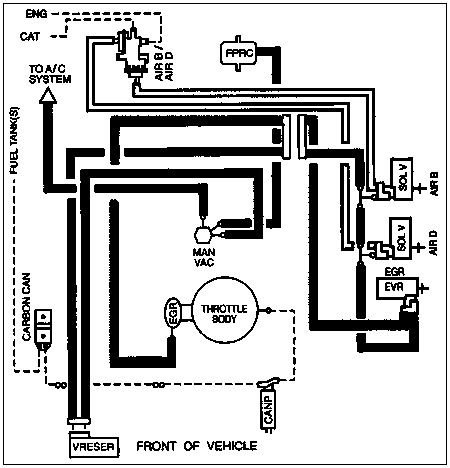
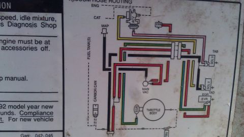

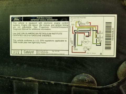
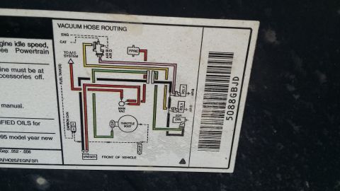
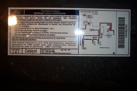
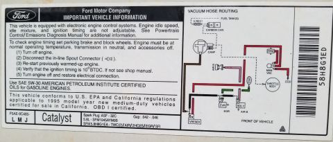

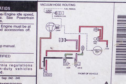
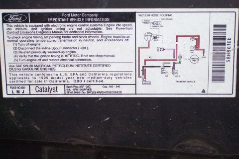
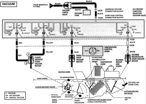
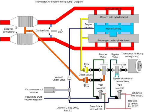
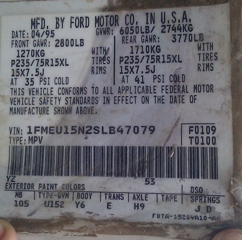







Vacuum hose routing diagram showing connections among throttle body, EGR, carbon canister, fuel tank and A/C system.
Part of 1992-1996 Ford Bronco Vacuum Routing Diagrams
This document is a vacuum hose routing diagram, apparently for a 1995 Ford Bronco (per the uploader's attribution and the Ford-style calibration filename F5AELMYV). The schematic shows the engine vacuum circuit layout as viewed with the front of the vehicle at the bottom (labeled 'FRONT OF VEHICLE'). Key components identified in the diagram include: the throttle body with EGR valve, manifold vacuum source (MAN VAC), the fuel pressure regulator control (FPRC), two solenoid valves (SOL V) controlling AIR B (air bypass) and AIR D (air diverter) functions for the secondary air injection system, the EGR vacuum regulator (EVR), the carbon canister (CARBON CAN) with its purge solenoid (CANP), a vacuum reservoir (VRESER), and connections to the fuel tank(s), the A/C system, engine (ENG), and catalyst (CAT) air points. Solid and dashed lines depict vacuum hoses and their routing between these components. A reader can use this diagram to trace, verify, or repair vacuum line connections for the emissions, EGR, evaporative, and air injection systems, and to identify which solenoids control the AIR B and AIR D circuits.
Is this accurate? Sign in to help verify it.
Frequently asked questions
- What components are shown on this vacuum routing diagram?
- The diagram shows the throttle body with EGR, manifold vacuum (MAN VAC), FPRC, two solenoid valves (SOL V) for AIR B and AIR D, the EGR vacuum regulator (EVR), carbon canister (CARBON CAN), canister purge solenoid (CANP), vacuum reservoir (VRESER), and lines to the fuel tank(s), A/C system, engine (ENG), and catalyst (CAT).
- How is the diagram oriented?
- The diagram is labeled 'FRONT OF VEHICLE' at the bottom, so the layout is drawn with the front of the vehicle toward the bottom of the page.
- Which solenoids control the AIR B and AIR D circuits?
- Two separate solenoid valves labeled 'SOL V' on the right side of the diagram control the AIR B and AIR D circuits, which route to a combined AIR B / AIR D valve near the top of the diagram.
- Where does the carbon canister connect?
- The carbon canister (CARBON CAN) on the left side connects via the routing shown to the fuel tank(s) line and to the canister purge solenoid (CANP) near the bottom of the diagram.
- Is there a vacuum reservoir in this system?
- Yes, a vacuum reservoir labeled 'VRESER' is shown at the bottom left of the diagram, and a line labeled 'TO A/C SYSTEM' branches off near the top left.






No comments yet.