Home/
Registry/
Ford/
Bronco/
1978-1979/
“buyers guide”/
Photo
supermotors.net/registry/media/987587
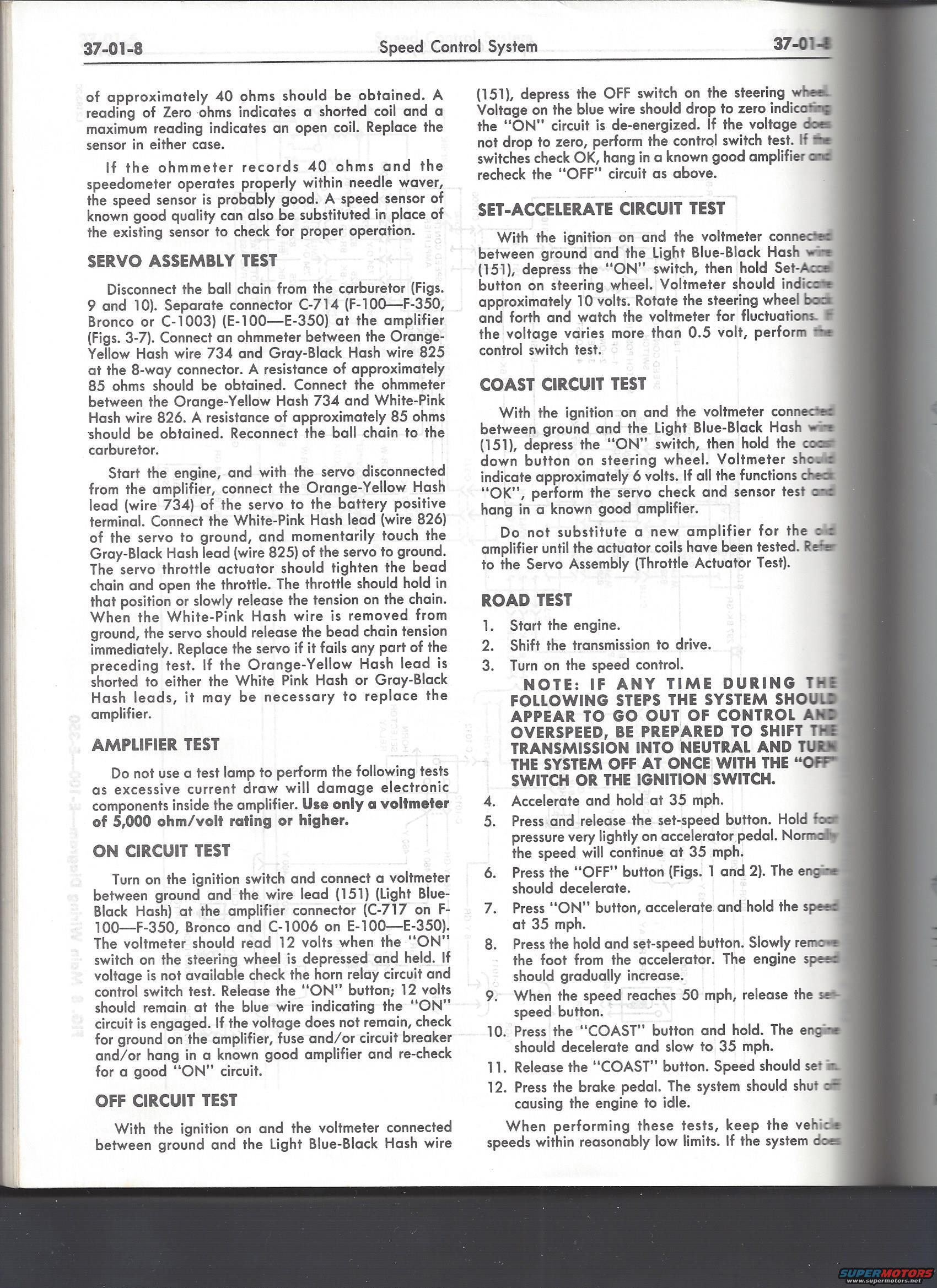
Ford Bronco F-100-F-350 Cruise Control Tests - Servo, Amplifier & Road Test 37-01-8
Reference · 1978-1979 BroncoAll 51 manual pages


Ford shop-manual text page covering cruise-control diagnostic procedures: ~40-ohm speed sensor check, ~85-ohm servo coil test, amplifier and circuit tests, plus road test steps.
Part of 1978-1979 Ford Bronco Manual Pages
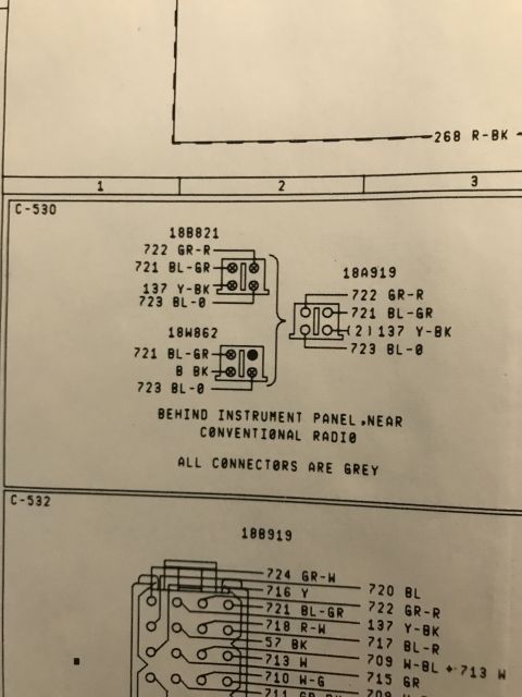
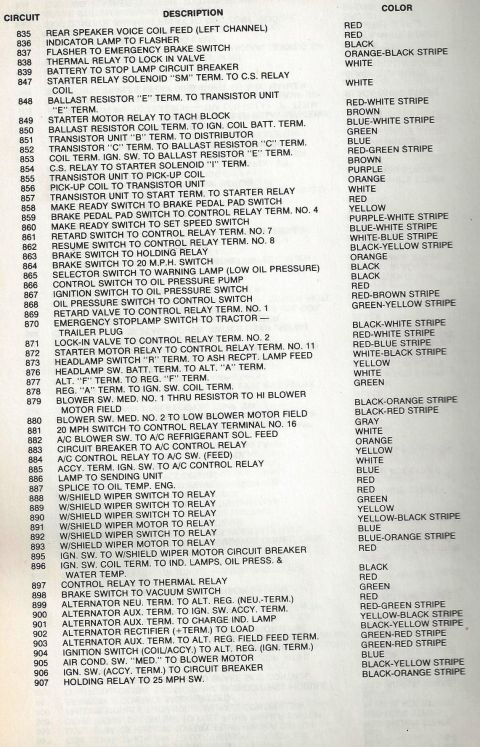
This is page 37-01-8 of a Ford shop manual section covering the Speed Control (cruise control) System for F-100 through F-350 trucks, Bronco, and E-100 through E-350 vans. It provides step-by-step diagnostic procedures: the Servo Assembly Test (disconnect the ball chain, separate connector C-714 or C-1003 at the amplifier, and check for approximately 85 ohms between Orange-Yellow Hash wire 734 and Gray-Black Hash wire 825, and between wire 734 and White-Pink Hash wire 826, plus a powered actuator test using the battery); the Amplifier Test warning to use only a voltmeter of 5,000 ohm/volt rating or higher; ON, OFF, Set-Accelerate, and Coast Circuit Tests measuring voltage on Light Blue-Black Hash wire 151 at connector C-717 (F-100-F-350, Bronco) or C-1006 (E-100-E-350), expecting 12 volts (ON), 0 volts (OFF), ~10 volts (Set-Accel), and ~6 volts (Coast); and a 12-step Road Test procedure at 35-50 mph, including a bold safety note about shifting to neutral or turning off the system if it overspeeds. Readers learn expected resistance and voltage values, wire colors and circuit numbers, and connector identifications for troubleshooting the cruise control amplifier, servo, and speed sensor.
Is this accurate? Sign in to help verify it.
Frequently asked questions
- What resistance should the cruise control servo show between wire 734 and wire 825?
- Approximately 85 ohms should be obtained between the Orange-Yellow Hash wire 734 and Gray-Black Hash wire 825 at the 8-way connector; the same ~85 ohms applies between wire 734 and White-Pink Hash wire 826.
- What voltage should be present on wire 151 during the ON circuit test?
- The voltmeter should read 12 volts on the Light Blue-Black Hash wire (151) when the "ON" switch on the steering wheel is depressed and held, and 12 volts should remain after releasing the button.
- Why can't a test lamp be used for the amplifier test?
- Excessive current draw will damage electronic components inside the amplifier. Only a voltmeter of 5,000 ohm/volt rating or higher should be used.
- What voltages indicate good Set-Accelerate and Coast circuits?
- With the ignition on and the voltmeter on wire 151, holding the Set-Accel button should show approximately 10 volts; holding the coast down button should show approximately 6 volts.
- What should happen when the brake pedal is pressed during the road test?
- The system should shut off, causing the engine to idle.






No comments yet.