Home/
Registry/
Ford/
Bronco/
1978-1979/
“buyers guide”/
Photo
supermotors.net/registry/media/987588
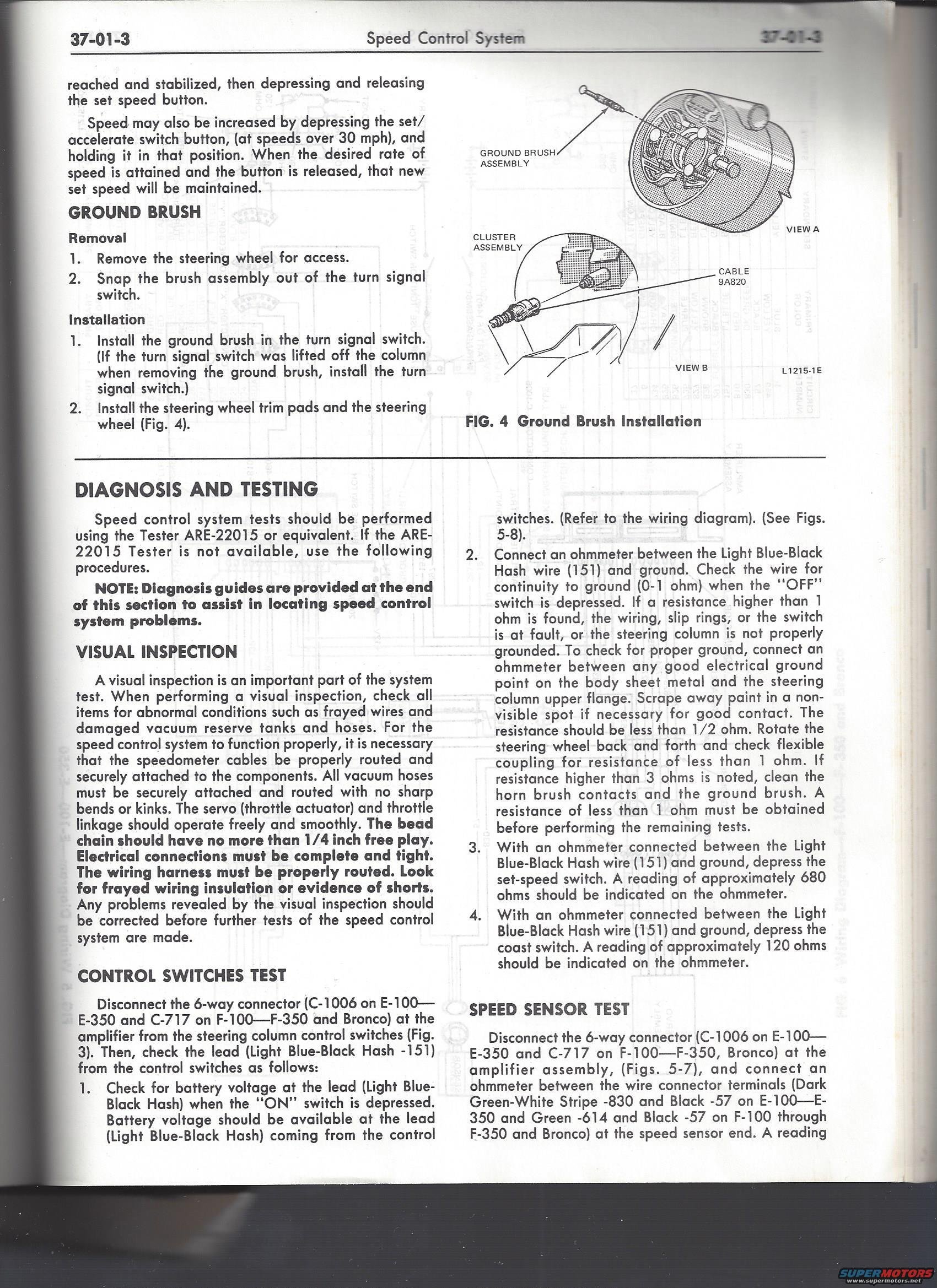
Ford Bronco/F-100-F-350 Cruise Control Diagnosis & Testing: Page 37-01-3
Reference · 1978-1979 BroncoAll 48 service procedures
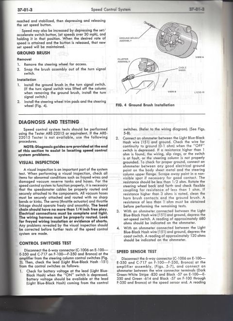
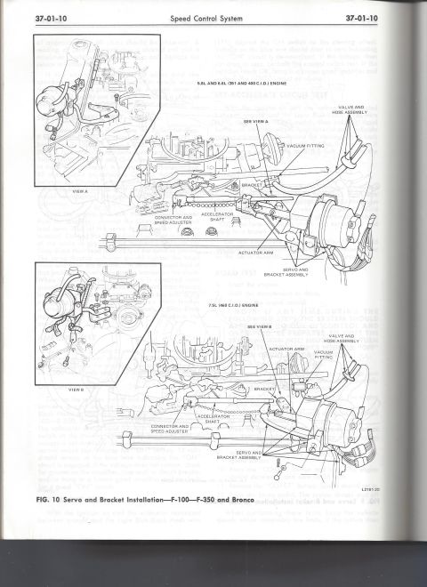
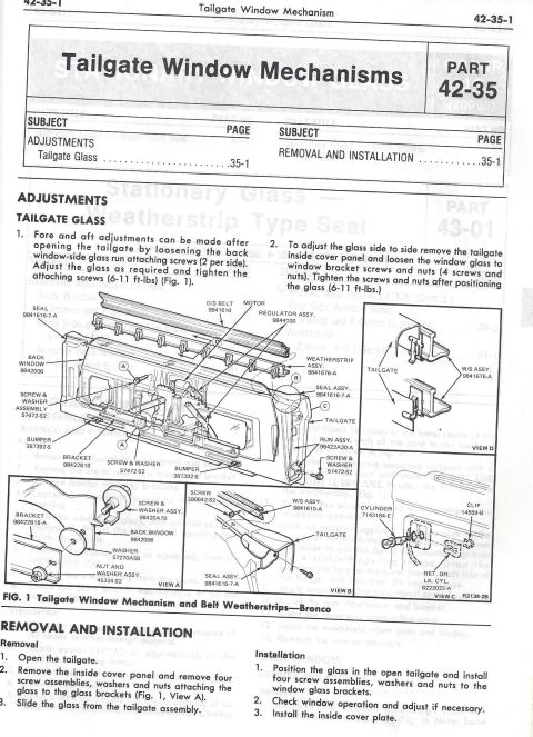
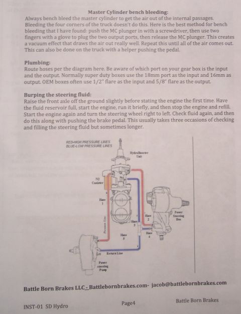
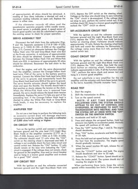


Speed control system service procedure covering ground brush removal/installation (via steering wheel and turn signal switch), control switch test, and speed sensor resistance test (680 ohms set-speed, 120 ohms coast).
Part of 1978-1979 Ford Bronco Service Procedures
This is page 37-01-3 of a Ford shop manual section on the Speed Control (cruise control) System, applicable to E-100 through E-350 vans, F-100 through F-350 trucks, and the Bronco. The page finishes a description of setting/increasing speed with the set/accelerate button, then gives removal and installation procedures for the ground brush in the turn signal switch, illustrated in Fig. 4 (Ground Brush Installation, showing the ground brush assembly, cluster assembly, and cable 9A820). The Diagnosis and Testing section recommends Tester ARE-22015 or equivalent and outlines a visual inspection: check for frayed wires, damaged vacuum tanks/hoses, properly routed speedometer cables, free servo/throttle linkage movement, bead chain free play no more than 1/4 inch, and tight electrical connections. The Control Switches Test details disconnecting the 6-way connector (C-1006 on E-100, E-350, C-717 on F-100, F-350 and Bronco) and checking the Light Blue-Black Hash wire (circuit 151): battery voltage with ON depressed, 0-1 ohm to ground with OFF depressed, approximately 680 ohms with set-speed depressed, and approximately 120 ohms with coast depressed. Ground checks specify less than 1/2 ohm to the steering column flange. The Speed Sensor Test begins, referencing circuits Dark Green-White Stripe 830, Black 57, and Green 614.
Is this accurate? Sign in to help verify it.
Frequently asked questions
- What resistance should the cruise control set-speed switch show on the Light Blue-Black Hash wire (151)?
- With an ohmmeter connected between the Light Blue-Black Hash wire (151) and ground, depressing the set-speed switch should show approximately 680 ohms.
- What reading indicates a good coast switch on this speed control system?
- With the ohmmeter between the Light Blue-Black Hash wire (151) and ground, depressing the coast switch should give approximately 120 ohms.
- Which connector is disconnected for the control switches and speed sensor tests?
- The 6-way connector at the amplifier: C-1006 on E-100, E-350 vans, and C-717 on F-100, F-350 trucks and Bronco.
- How much free play is allowed in the speed control bead chain?
- The bead chain should have no more than 1/4 inch free play.
- How is the ground brush removed and installed?
- Remove the steering wheel for access and snap the brush assembly out of the turn signal switch. To install, put the ground brush in the turn signal switch (reinstalling the turn signal switch if it was lifted off the column), then install the steering wheel trim pads and steering wheel.






No comments yet.