Home/
Registry/
Ford/
Bronco/
1992-1996/
“Eddie Bauer”/
Photo
supermotors.net/registry/media/1000153
1992-96 Ford Bronco 5.8L Thermactor Air Injection Hoses - Exploded Parts Diagram

Reference · 1992-1996 BroncoAll 169 exploded parts diagrams
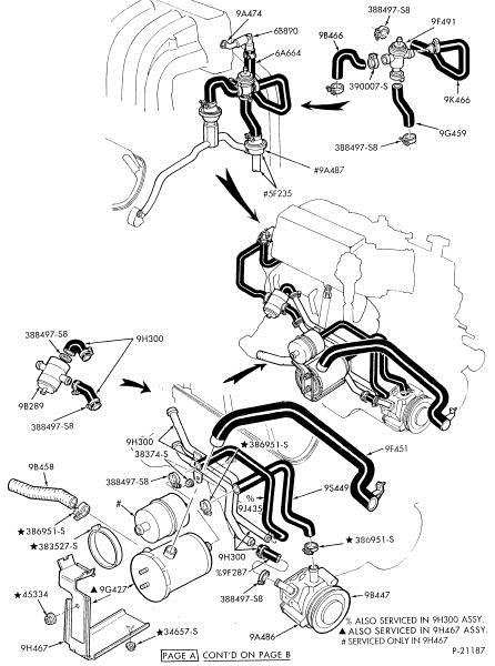
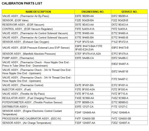


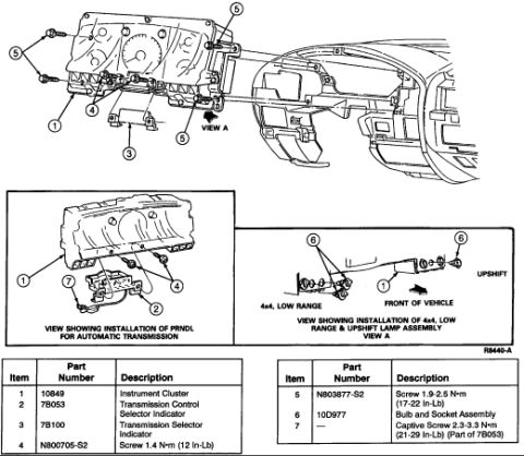
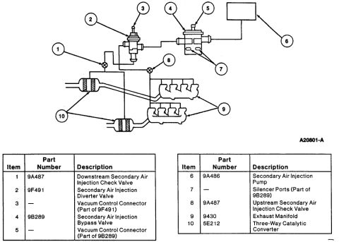
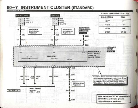

Exploded parts diagram of engine vacuum/emission hoses, valves and connectors with Ford part numbers.
Part of 1992-1996 Ford Bronco Exploded Parts Diagrams
This is a scanned Ford exploded parts diagram (drawing number P-21187, marked 'Page A, cont'd on Page B') showing the thermactor (secondary air injection) hose routing and related components on a V8 engine, uploaded as applying to 1992-96 Ford Bronco 5.8L trucks. The illustration uses Ford base part-number callouts to identify each hose, clamp, fitting, valve, and bracket. Major callouts include the air pump (9A486), air bypass/control valves (9B466, 9F491, 9B289), hoses and tubes (9A474, 6A664, 9K466, 9G459, 9A487, 9F451, 9S449, 9J435, 9F287, 9B458), check-valve/tube hardware (68890, 5F235, 9G427), hose assemblies 9H300 and 9H467, and fastener/clamp standard part numbers (388497-S8, 390007-S, 38374-S, 386951-S, 383527-S, 45334, 34657-S). Footnote symbols indicate service groupings: '%' items are also serviced in the 9H300 assembly, '▲' items are also serviced in the 9H467 assembly, and '#' items are serviced only in 9H467. A reader can use this page to identify individual thermactor system hoses and clamps by base part number, see how they route between the air pump, valves, and exhaust manifolds, and determine which pieces come only as part of larger hose assemblies.
Is this accurate? Sign in to help verify it.
Frequently asked questions
- What Ford base part number is the thermactor air pump in this diagram?
- The air pump at the lower right of the diagram is labeled 9A486.
- Which parts are serviced only as part of a larger assembly?
- Items marked '#' are serviced only in the 9H467 assembly; items marked '%' are also serviced in the 9H300 assembly; items marked '▲' are also serviced in the 9H467 assembly.
- What clamp part number is used repeatedly on the thermactor hoses?
- Clamp part number 388497-S8 appears at multiple hose connections throughout the diagram; 390007-S is also shown at one connection.
- What are the main hose assembly part numbers shown?
- The two main hose assemblies referenced are 9H300 and 9H467, with individual hoses/tubes such as 9A474, 6A664, 9K466, 9G459, 9A487, 9F451, 9S449, 9J435, 9F287, and 9B458.
- Is this the complete diagram?
- No: the banner at the bottom reads 'PAGE A, CONT'D ON PAGE B', so this is the first page of a two-page illustration (drawing P-21187).






No comments yet.