Home/
Registry/
Ford/
Bronco/
1992-1996/
“Eddie Bauer”/
Photo
supermotors.net/registry/media/1000232
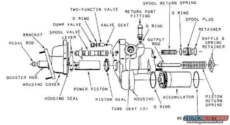
Ford Bronco Hydro-Boost Brake Booster Exploded Parts Diagram
Reference · 1992-1996 BroncoAll 169 exploded parts diagrams
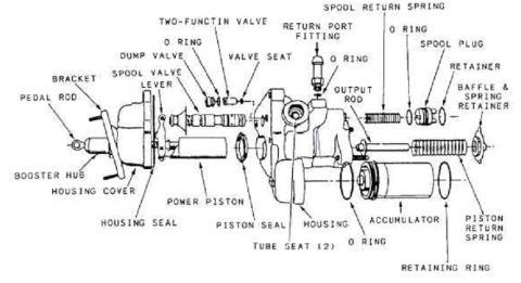












Exploded parts diagram of a hydro-boost brake booster showing spool valve, power piston, accumulator and seals.
Part of 1992-1996 Ford Bronco Exploded Parts Diagrams
This document is an exploded parts diagram of a Hydro-Boost hydraulic brake booster assembly, uploaded to a 1994 Ford Bronco gallery on SuperMotors.net. The illustration shows the booster disassembled along its axis with callout labels identifying each component and its position in the assembly. From left to right, the labeled parts include the pedal rod, booster hub, bracket, housing cover, spool valve lever, dump valve, two-function valve (spelled 'TWO-FUNCTIN VALVE' in the scan) with its O-ring and valve seat, housing seal, power piston, piston seal, and the main housing with its return port fitting and O-ring, plus two tube seats. On the right side, the diagram shows the output rod, spool return spring, O-rings, spool plug, retainer, baffle & spring retainer, accumulator with O-ring and retaining ring, and the piston return spring. The diagram contains no part numbers, torque specifications, year/model statements, or text beyond the component names. A reader can use it to identify the names and relative assembly order of all internal and external components when disassembling, inspecting, or rebuilding a hydroboost brake booster unit.
Is this accurate? Sign in to help verify it.
Frequently asked questions
- What components are inside a hydroboost brake booster according to this diagram?
- The diagram labels the pedal rod, booster hub, bracket, housing cover, spool valve lever, dump valve, two-function valve with O-ring and valve seat, power piston, housing seal, piston seal, housing, tube seats (2), return port fitting, output rod, spool return spring, spool plug, retainer, baffle & spring retainer, accumulator, retaining ring, O-rings, and piston return spring.
- How many tube seats does the hydroboost housing have?
- The diagram calls out 'TUBE SEAT (2)', indicating two tube seats in the housing.
- Where is the accumulator located in the hydroboost assembly?
- The accumulator is shown at the lower right of the housing, sealed with an O-ring, held by a retaining ring, and associated with the piston return spring.
- What parts are associated with the spool valve in this diagram?
- The spool valve section shows a spool valve lever, spool return spring, an O-ring, spool plug, and retainer.
- Does this diagram include part numbers or torque specs?
- No. It only shows component names on an exploded view; no part numbers, torque values, or year/model information are printed on it.






No comments yet.