Home/
Registry/
Ford/
Bronco/
1992-1996/
“Eddie Bauer”/
Photo
supermotors.net/registry/media/1021985
Ford Engine Block Ground / Negative Battery Cable Diagram - Views B, D, E, F

Reference · 1992-1996 BroncoAll 169 exploded parts diagrams
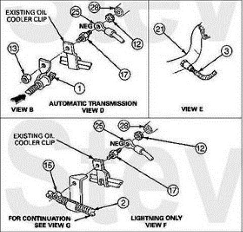












Exploded views of battery cable routing, oil cooler clip and connector hardware with numbered callouts.
Part of 1992-1996 Ford Bronco Exploded Parts Diagrams
This document is an exploded-parts illustration showing engine block ground / negative battery cable attachment points, presented as multiple labeled views. View B and View D (marked "AUTOMATIC TRANSMISSION") show a negative cable eyelet labeled "NEG" secured with hardware (callouts 25, 28, 12, 17) to a stud that also retains an "EXISTING OIL COOLER CLIP," plus a lower ground stud arrangement (callouts 13 and 1). View E shows cable routing with callouts 21 and 3. View F, marked "LIGHTNING ONLY," shows a similar NEG cable attachment at the oil cooler clip stud (callouts 25, 28, 12, 17) along with a spring/boot component (callout 15) on a lower stud (callout 2), with a note reading "FOR CONTINUATION SEE VIEW G." A reader can learn where the negative battery/ground cable eyelet fastens at the engine block, that the attachment shares a stud with an existing oil cooler clip, that a distinct configuration applies to automatic transmission vehicles versus Lightning models, and that this page is part of a multi-view set continuing in View G. No part numbers, torque values, or year statements are visible; callout numbers reference a legend not shown on this page.
Is this accurate? Sign in to help verify it.
Frequently asked questions
- Where does the negative battery cable eyelet attach on the engine block?
- Per Views D and F, the eyelet marked "NEG" attaches to a stud at the location of the existing oil cooler clip, secured with hardware shown as callouts 25, 28, 12, and 17.
- Is there a different ground cable configuration for certain models?
- Yes. View D is labeled "AUTOMATIC TRANSMISSION" and View F is labeled "LIGHTNING ONLY," indicating different configurations for those applications.
- Is this the complete diagram set?
- No. View F includes the note "FOR CONTINUATION SEE VIEW G," so at least one additional view exists on another page.
- Does the diagram identify specific part numbers or torque specs?
- No. It uses numbered callouts (1, 2, 3, 12, 13, 15, 17, 21, 25, 28) that reference a parts legend not shown on this page, and no torque values appear.






No comments yet.