Home/
Registry/
Ford/
Bronco/
1992-1996/
“Eddie Bauer”/
Photo
supermotors.net/registry/media/1027528
Ford Bronco Side Body Panel Template Blueprint with Hole Locations & Dimensions
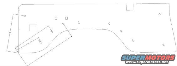
Engineering line drawing of a panel showing its contour, hole locations and cutouts.
Part of 1992-1996 Ford Bronco Blueprints
This document is a CAD-style blueprint or template drawing of an automotive side body panel, uploaded to a 1994 Ford Bronco gallery under the filename 'side panel.jpg'. The drawing shows the full perimeter outline of the panel, including a notch cut along the top edge, a large wheel-arch curve along the bottom, two small rectangular cutouts near the upper middle, one larger rectangular cutout on the left side, and roughly a dozen circular hole locations (in single and paired configurations) distributed across the panel. Several dimension lines with arrowheads are drawn across the left and lower portions of the panel, but the accompanying measurement labels are rendered at very small size and are only partially legible; readable fragments suggest values around 85 ½ inches, 85 ⅞ inches, 100-plus inches, and a small dimension near 10 inches. No title block, part numbers, year, make, model, or scale notation appears anywhere on the drawing. A reader can learn the general shape and hole layout of the panel for use as a fabrication or replication template, but would need a higher-resolution copy to extract exact measurements.
Is this accurate? Sign in to help verify it.
Frequently asked questions
- What does this blueprint show?
- It shows the outline of a vehicle side panel with rectangular cutouts, circular hole locations, and several dimension lines marked with arrowheads.
- Are exact measurements readable on this drawing?
- Only partially. Dimension labels are present but very small; readable fragments include values around 85 ½ in, 85 ⅞ in, and 100+ in.
- Does the drawing identify the vehicle year, make, or model?
- No. There is no title block, part number, year, or model information visible anywhere on the drawing.
- What features are marked on the panel?
- Two small rectangular cutouts near the top center, one larger rectangular cutout on the left, a bottom wheel-arch curve, a top-edge notch, and numerous circular holes in single and paired arrangements.
Comments
More from this build







No comments yet.