Home/
Registry/
Ford/
Bronco/
1992-1996/
1994 Ford Bronco/
Photo
supermotors.net/registry/media/1078308
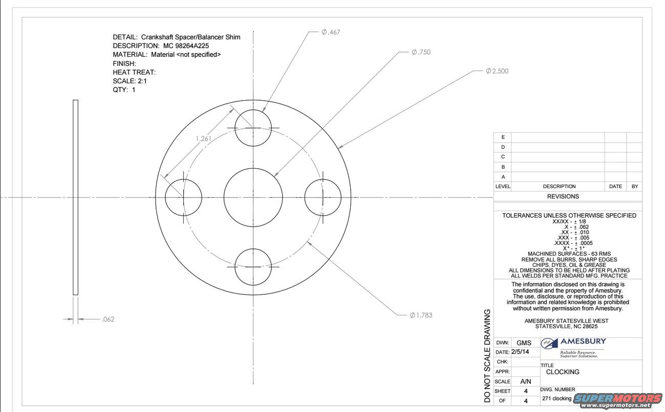
Crankshaft Spacer/Balancer Shim Blueprint MC 98264A225 - Dimensions & Specs
Reference · 1992-1996 BroncoAll 81 blueprints


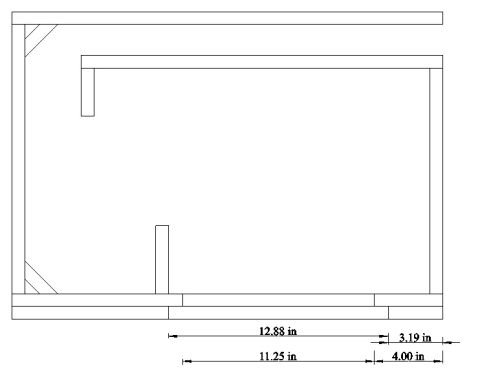
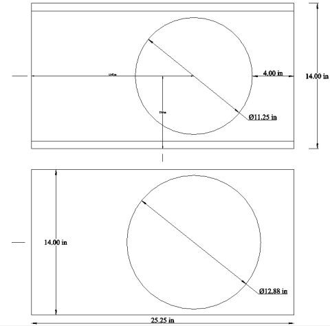
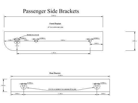
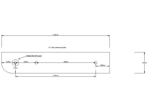






Dimensioned engineering blueprint of a crankshaft spacer/balancer shim with tolerances and title block.
Part of 1992-1996 Ford Bronco Blueprints
This document is a mechanical engineering blueprint (sheet 4 of 4) produced by Amesbury Statesville West of Statesville, NC 28625, titled "CLOCKING" (drawing number "271 clocking"), drawn by GMS on 2/5/14. It details a Crankshaft Spacer/Balancer Shim, description MC 98264A225, quantity 1, drawn at 2:1 scale, with material, finish, and heat treatment not specified. The front view shows a circular disc with an outside diameter of Ø2.500, a Ø.750 center bore, and four Ø.467 holes arranged on a Ø1.783 bolt circle (radial dimension 1.261 shown). The side view specifies a thickness of.062. The drawing includes standard tolerance notes (XX/XX ±1/8.X ±.062.XX ±.010.XXX ±.005.XXXX ±.0005, angles ±1°), machined surface finish of 63 RMS, requirements to remove burrs, sharp edges, chips, dyes, oil and grease, that all dimensions be held after plating, and that welds follow standard manufacturing practice. A blank revisions table (levels A-E) and a confidentiality statement from Amesbury are included. A reader can learn the exact dimensions needed to fabricate or verify this crankshaft spacer/balancer shim. The drawing does not state any vehicle year, make, model, or engine applicability.
Is this accurate? Sign in to help verify it.
Frequently asked questions
- What are the dimensions of the crankshaft spacer/balancer shim in this blueprint?
- The shim has a Ø2.500 outside diameter, a Ø.750 center bore, four Ø.467 holes on a Ø1.783 bolt circle, and a thickness of .062.
- What part number or description identifies this shim?
- The drawing description is MC 98264A225, titled "CLOCKING," drawing number "271 clocking," detail name "Crankshaft Spacer/Balancer Shim."
- What material is specified for the shim?
- The drawing lists "Material <not specified>" and leaves the finish and heat treat fields blank.
- What tolerances apply to the dimensions on this drawing?
- Unless otherwise specified: XX/XX ±1/8, .X ±.062, .XX ±.010, .XXX ±.005, .XXXX ±.0005, and angles ±1°, with machined surfaces at 63 RMS.
- Who produced this drawing and when?
- It was drawn by GMS on 2/5/14 at Amesbury Statesville West, Statesville, NC 28625; it is sheet 4 of 4.






No comments yet.