Home/
Registry/
Hyundai/
Genesis Coupe/
2010-2016/
“Coupe”/
Photo
supermotors.net/registry/media/1030563
2010 Hyundai Genesis EVAP Canister, CCV & FTPS Location Diagram
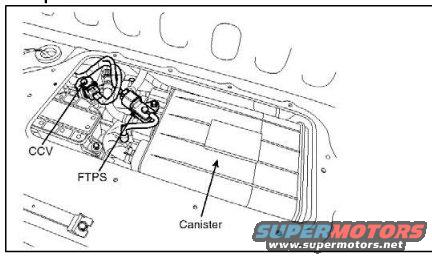
Schematic line drawing showing the location of the EVAP canister, CCV and FTPS components on the fuel tank.
Part of 2010-2016 Hyundai Genesis Coupe Schematics
This document is a line-drawing schematic showing the location of evaporative emissions (EVAP) system components on the underside of a vehicle, uploaded to a 2010 Hyundai Genesis gallery. The illustration depicts the underbody area with three labeled components identified by arrows: the CCV (canister close valve), the FTPS (fuel tank pressure sensor), and the Canister (the EVAP charcoal canister). The CCV and FTPS are shown mounted together on the left side of the assembly with associated hoses and wiring, while the large rectangular canister occupies the central portion of the drawing. No part numbers, torque values, connector pinouts, or year/model applicability statements are printed on the image. A reader can use this diagram to visually locate the EVAP canister and its attached CCV and FTPS components under the vehicle, which is useful when diagnosing evaporative emission trouble codes or servicing the fuel vapor system. The drawing contains only the three component labels and no other text.
Is this accurate? Sign in to help verify it.
Frequently asked questions
- Where is the EVAP canister located on the 2010 Hyundai Genesis according to this diagram?
- The diagram shows the canister mounted under the vehicle as a large rectangular unit in the center of the underbody assembly, with the CCV and FTPS attached at one end.
- What components are labeled in this schematic?
- Three components are labeled: the CCV, the FTPS, and the Canister.
- Are the CCV and FTPS mounted near each other?
- Yes, the diagram shows the CCV and FTPS mounted close together at the left end of the canister assembly, connected by hoses/wiring.
Comments
More from this build









No comments yet.