Home/
Registry/
Hyundai/
Genesis Coupe/
2010-2016/
“Coupe”/
Photo
supermotors.net/registry/media/1030564
2010 Hyundai Genesis Fuel Delivery System Components Location Diagram

Reference · 2010-2016 Genesis CoupeAll 14 exploded parts diagrams
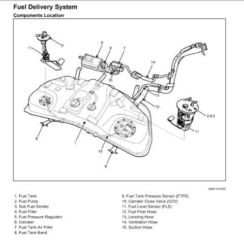
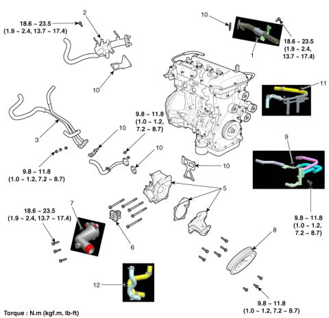
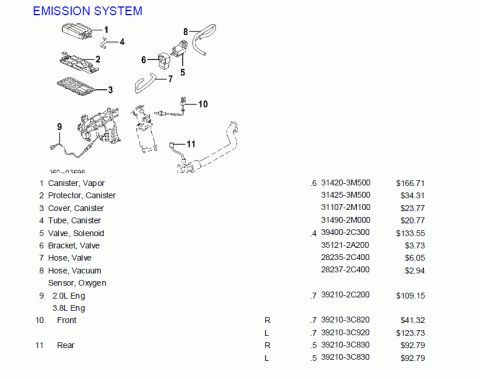
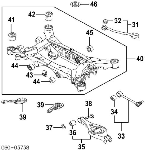
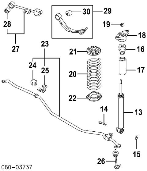








Components-location drawing of the fuel delivery system showing tank, pump, filter, sender and sensors with a numbered parts legend.
Part of 2010-2016 Hyundai Genesis Coupe Exploded Parts Diagrams
This document is a components-location page from a service manual for the Fuel Delivery System, uploaded to a 2010 Hyundai Genesis gallery. It presents an exploded/isometric diagram of the fuel tank assembly with fifteen numbered callouts and a matching legend. Identified components include the fuel tank (1), fuel pump (2), sub fuel sender (3), fuel filter (4), and fuel pressure regulator (5), with items 2, 4, and 5 grouped together on the fuel pump module in the diagram. Evaporative emissions parts are also shown: the canister (6), fuel tank air filter (7), fuel tank pressure sensor FTPS (9), and canister close valve CCV (10). Mounting and plumbing items include the fuel tank bands (8, shown in two locations), fuel level sensor FLS (11, shown on both sender assemblies), fuel filler hose (12), leveling hose (13), ventilation hose (14), and suction hose (15). The diagram reference code SBKF19152N appears at the lower right. A reader can use this page to identify each fuel system component by name and see where it mounts on or around the saddle-style fuel tank, useful when servicing the fuel pump, senders, canister, or evaporative hoses.
Is this accurate? Sign in to help verify it.
Frequently asked questions
- Where is the fuel pressure regulator located on the Hyundai Genesis fuel system?
- Per the diagram, the fuel pressure regulator (item 5) is grouped with the fuel pump (2) and fuel filter (4) as part of the fuel pump module assembly that mounts into the fuel tank.
- What evaporative emissions components are shown in this fuel delivery system diagram?
- The diagram shows the canister (6), fuel tank air filter (7), fuel tank pressure sensor FTPS (9), and canister close valve CCV (10).
- How many fuel level senders does this fuel tank have?
- Two sender assemblies are shown: the main fuel pump assembly (items 2, 4, 5) and a sub fuel sender (item 3), with a fuel level sensor FLS (item 11) indicated on both.
- What hoses connect to the fuel tank in this diagram?
- The fuel filler hose (12), leveling hose (13), ventilation hose (14), and suction hose (15).
- How is the fuel tank secured according to this diagram?
- The tank is held by fuel tank bands (item 8), shown at two mounting locations on the diagram.

No comments yet.