Home/
Registry/
Ford/
Bronco/
1987-1991/
“Eddie Bauer”/
Photo
supermotors.net/registry/media/1040764
1995 Ford Bronco Instrument Cluster Wiring Diagram 60-2 - Temp & Oil Gauges

Reference · 1987-1991 BroncoAll 175 wiring diagrams
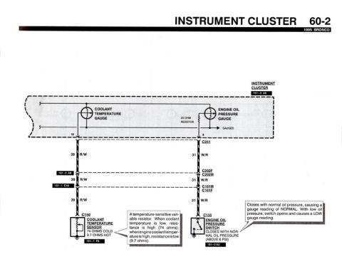














Wiring diagram of the instrument cluster showing coolant temperature and oil pressure gauge circuits with color-coded wires.
Part of 1987-1991 Ford Bronco Wiring Diagrams
This is page 60-2 of the 1995 Ford Bronco electrical/wiring diagram manual, covering the Instrument Cluster gauge circuits for the coolant temperature gauge and engine oil pressure gauge. The diagram shows the instrument cluster (component location reference 151-3 A6) containing the coolant temperature gauge and the engine oil pressure gauge, which includes a 20 ohm resistor in its circuit. From cluster pins 10 and 8, the circuits run through connector C251 on circuit 39 R/W (red/white, coolant temperature) and circuit 31 W/R (white/red, oil pressure). Both wires pass through connectors C202F/C202M (location 151-2 A8) and C101M/C101F (location 151-1 C10). Circuit 39 terminates at C150, the coolant temperature sensor (location 151-1 F9), described as a temperature-sensitive variable resistor: 74 ohms cold, 9.7 ohms hot. Circuit 31 terminates at C135, the engine oil pressure switch (location 151-2 A3), which closes with normal oil pressure (above 6 PSI) to produce a NORMAL gauge reading, and opens with low oil pressure to produce a LOW gauge reading. This page is useful for diagnosing inaccurate temperature or oil pressure gauge readings, verifying sensor resistance values, and tracing wire colors and connector locations.
Is this accurate? Sign in to help verify it.
Frequently asked questions
- What wire color is the coolant temperature gauge circuit on a 1995 Bronco?
- Circuit 39, colored R/W (red/white), runs from the instrument cluster coolant temperature gauge through connectors C251, C202F/C202M, and C101M/C101F to the coolant temperature sensor C150.
- What resistance should the 1995 Bronco coolant temperature sensor read?
- The coolant temperature sensor (C150) is a temperature-sensitive variable resistor: about 74 ohms cold and 9.7 ohms hot. Resistance is high when coolant is cold and low when the engine is hot.
- How does the 1995 Bronco engine oil pressure switch work?
- The engine oil pressure switch (C135) closes with normal oil pressure (above 6 PSI), causing a NORMAL gauge reading. With low oil pressure the switch opens, causing a LOW gauge reading.
- What wire circuit feeds the oil pressure gauge on a 1995 Bronco?
- Circuit 31, colored W/R (white/red), runs from the oil pressure gauge (which has a 20 ohm resistor in the cluster) through connectors C251, C202F/C202M, and C101M/C101F to the oil pressure switch C135.
- What connectors are in the temperature and oil pressure gauge circuits?
- Both circuits pass through C251, then C202F/C202M (location 151-2 A8) and C101M/C101F (location 151-1 C10), ending at C150 (coolant temp sensor, 151-1 F9) and C135 (oil pressure switch, 151-2 A3).






No comments yet.